Summary of Smart Wi-Fi Video Doorbell using ESP32 and Camera
This article details the construction of a Smart Wi-Fi Video Doorbell using an ESP32-CAM module. The system allows users to receive live video streams, play custom songs, and get SMS notifications when the doorbell button is pressed. It integrates with IFTTT for automation and uses a 3D-printed casing for housing. The project demonstrates how IoT can enhance home security by connecting physical actions to digital alerts via Wi-Fi.
Parts used in the Smart Wi-Fi Video Doorbell:
- ESP32-CAM
- FTDI Programming Board
- 220V AC to 5V DC Converter
- Buzzer
- Push Button
- LED (2)
Nowadays, Security system is one of the most researched fields and with increasing security threats, companies are launching new smart security products to combat these threats. IoT is an added advantage in this field which can automatically trigger an event, like calling the police, fire brigade or your neighbor, in case of any emergency. We previously built many security systems like Raspberry Pi Visitor monitoring system, video surveillance camera, wireless doorbell, IoT based Door Security Alarm etc. Today we will use ESP32 and camera to build a Smart Wi-Fi door bell.
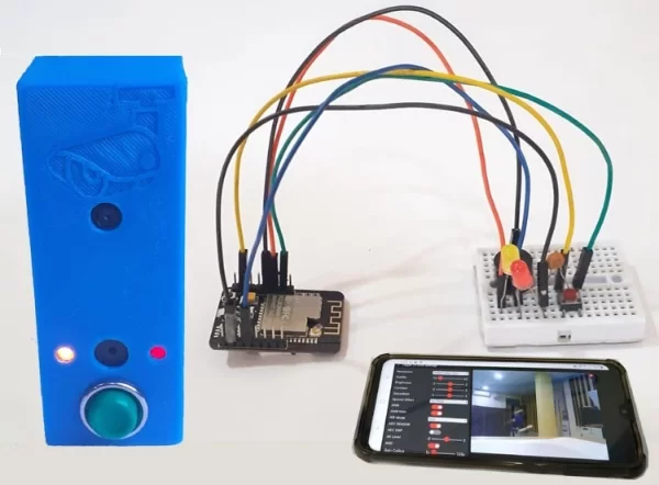
In another tutorial, we have learned about ESP32-CAM and how to use it for video streaming, now we will make a Smart Wi-Fi Video Doorbell using ESP32-CAM. This Smart doorbell can easily be powered by an AC socket and whenever someone at the door presses the doorbell button, it will play a specific song on your phone and sends a text message with a link of video streaming page where you can see the person at the door from anywhere in world.
Components Required
- ESP32-CAM
- FTDI Programming Board
- 220V AC to 5V DC Converter
- Buzzer
- Push Button
- LED (2)
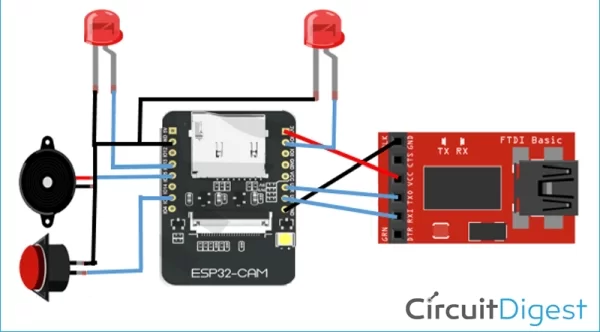
Circuit Diagram
Circuit diagram for this Smart Wi-Fi Doorbell is very simple, just connect two LEDs, a push button and a buzzer to ESP32 GPIO pins. A buzzer is used to make a sound whenever the button is pressed. One LED is used to indicate the power status, and the other LED is used to indicate the network status. Network LED will be in a high state if ESP is connected to a network otherwise, it will blink.
IFTTT Setup for Wi-Fi Doorbell
IFTTT is a free web-based service that allows users to create chains of simple conditional statements, called “recipes”, which are triggered based on changes to other web services such as Gmail, Facebook, Instagram, and Pinterest. IFTTT is an abbreviation of “If This Then That”.
In this project, IFTTT is used to send an Email whenever the temperature or humidity goes beyond a predefined limit. We previously used IFTTT in many IoT based projects to send emails or SMS on particular events like on excessive electricity consumption, on high pulse rate, on intruder entry, etc.
First login to IFTTT with your credentials or Sign Up if you don’t have an account on it.
Now search for ‘Webhooks’ and click on the Webhooks in Services section.

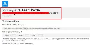
Now, in the Webhooks window, click on ‘Documentation’ in the upper right corner to get the private key.
Copy this key. It will be used in the program.
After getting the private key, now we will create an applet using Webhooks and Email services. To create an applet click on your profile and then click on ‘Create.’
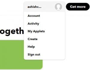
Now in the next window, click on the ‘This’ icon.
![]()
Now search for Webhooks in the search section and click on ‘Webhooks.’

Now choose ‘Receive a Web Request’ trigger and in the next window, enter the event name as button_pressed and then click on create a trigger.
Now to complete the applet, click on ‘That’ to create a reaction for the button_pressed event.

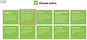
Here we will play a specific song on the phone when the IoT doorbell button is pressed. For that search for ‘Android device’ in the search section.

Now in Android Device, choose ‘Play a specific song’ trigger.
Now enter the song title that you want to play when the doorbell button is pressed. In my case, I’m playing a song named ‘123’ from my Google play music. You can also use Spotify or other music apps.
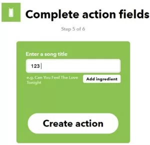
After that, click on ‘Create action’ and then ‘Finish’ to complete the process.
Now create another applet to send a message with the webpage link to the phone when the doorbell button is pressed.
So to create this applet choose ‘Webhooks’ in ‘this’ section and in ‘that’ section choose ‘Android SMS.’
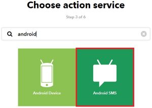
Now it will ask to enter the phone number and message body. For this Wi-Fi doorbell project, we are sending a message with the Webserver link so that you can see the live video streaming directly.
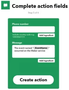
Code Explanation
Complete code along with the video for this Wi-Fi doorbell camera is given at the end of this document. It can also be downloaded from here. Below we are explaining some important parts of the code.
First, include all the required library files for this code.
#include "esp_camera.h"
#include <WiFi.h>
Then enter the Wi-Fi credentials.
const char* ssid = "Wi-Fi Name";
const char* password = "Wi-Fi Password";
After that, enter the IFTTT hostname and private key that you copied from the IFTTT website.
const char *host = "maker.ifttt.com";
const char *privateKey = "Your Private Key";
Define all the pins that you are using in this project. I’m using the GPIO 2, 14 and 15 pins to connect the push button, LED and buzzer.
const int buttonPin = 2;
const int led1 = 14;
const int buzzer = 15;
Inside the void setup loop, define the button pin as input and LED and buzzer pins as output.
void setup() {
  pinMode(buttonPin, INPUT);
  pinMode(led1, OUTPUT);
  pinMode(buzzer, OUTPUT);
It will try to connect to Wi-Fi using the given credentials, and when connected to a network LED state will change from low to high.
WiFi.begin(ssid, password);
  int led = LOW;
  while (WiFi.status() != WL_CONNECTED) {
    delay(500);
    Serial.print(".");
    digitalWrite(led1, led);
    led = !led;
  }
  Serial.println("");
  Serial.println("WiFi connected");
  digitalWrite(led1, HIGH);
While disconnected from a network ESP32 will restart until it connects to a network.
while (WiFi.status() == WL_DISCONNECTED) {
    ESP.restart();
    digitalWrite(led1, LOW);
    Serial.print("Connection Lost");
ESP32 will read the button state, and if the button is in the LOW state (pulled high), i.e., a button has been pressed, it sends the event and turns on the buzzer for 3 seconds.
int reading = digitalRead(buttonPin);
if (buttonState == LOW) {
        send_event("button_pressed");
        Serial.print("button pressed");
        digitalWrite(buzzer, HIGH);
        delay(3000);
          digitalWrite(buzzer, LOW);
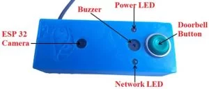
3D Printed Casing for Smart Wi-Fi Doorbell
Here I designed a 3D printed casing for this wireless doorbell camera. For that, I measured the dimensions of the ESP32 board, Pushbutton, Buzzer and LED using my vernier caliper and the design looked something like this below once it was done.
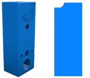
After that, I exported it as an STL file, sliced it based on printer settings, and finally printed it. The STL file is available for download from Thingiverse and you can print your own casing using it.
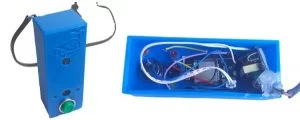
After printing the case, I assembled the circuit into my casing and everything was a nice fit, as you can see here.
If you want to know more about a 3D printer and how it works you can read this article on Beginners Guide to Getting Started with 3D Printing and can also check our other projects where we used 3D printed casings like Biped Robot, Robotic Arm, etc.
Testing the Smart Wi-Fi Doorbell
After assembling the circuit, power the Doorbell using an AC socket. Now whenever the IoT doorbell button is pressed the smartphone starts playing a song named ‘123,’ and a message will be received with a link of a webpage as shown below, where the live video feed can be seen.
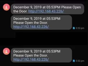
Complete code and working video for this Smart Wi-Fi doorbell can be found at the end of the document or you can download the code from here. If you have any queries regarding this project, leave them in the comment section.
Code
#include “esp_camera.h”
#include <WiFi.h>
//
// WARNING!!! Make sure that you have either selected ESP32 Wrover Module,
// or another board which has PSRAM enabled
//
// Select camera model
//#define CAMERA_MODEL_WROVER_KIT
//#define CAMERA_MODEL_ESP_EYE
//#define CAMERA_MODEL_M5STACK_PSRAM
//#define CAMERA_MODEL_M5STACK_WIDE
#define CAMERA_MODEL_AI_THINKER
#include “camera_pins.h”
void send_event(const char *event);
const char* ssid = “Galaxy-M20”;
const char* password = “ac312124”;
const char *host = “maker.ifttt.com”;
const char *privateKey = “hUAAAz0AVvc6-NW1UmqWXXv6VQWmpiGFxx3sV5rnaM9”;
const int buttonPin = 2;
int buttonState; // the current reading from the input pin
int lastButtonState = LOW; // the previous reading from the input pin
const int led1 = 14;
const int buzzer = 15;
long lastDebounceTime = 0; // the last time the output pin was toggled
long debounceDelay = 50; // the debounce time; increase if the output flickers
void startCameraServer();
void setup() {
pinMode(buttonPin, INPUT);
pinMode(led1, OUTPUT);
pinMode(buzzer, OUTPUT);
Serial.begin(115200);
Serial.setDebugOutput(true);
Serial.println();
camera_config_t config;
config.ledc_channel = LEDC_CHANNEL_0;
config.ledc_timer = LEDC_TIMER_0;
config.pin_d0 = Y2_GPIO_NUM;
config.pin_d1 = Y3_GPIO_NUM;
config.pin_d2 = Y4_GPIO_NUM;
config.pin_d3 = Y5_GPIO_NUM;
config.pin_d4 = Y6_GPIO_NUM;
config.pin_d5 = Y7_GPIO_NUM;
config.pin_d6 = Y8_GPIO_NUM;
config.pin_d7 = Y9_GPIO_NUM;
config.pin_xclk = XCLK_GPIO_NUM;
config.pin_pclk = PCLK_GPIO_NUM;
config.pin_vsync = VSYNC_GPIO_NUM;
config.pin_href = HREF_GPIO_NUM;
config.pin_sscb_sda = SIOD_GPIO_NUM;
config.pin_sscb_scl = SIOC_GPIO_NUM;
config.pin_pwdn = PWDN_GPIO_NUM;
config.pin_reset = RESET_GPIO_NUM;
config.xclk_freq_hz = 20000000;
config.pixel_format = PIXFORMAT_JPEG;
//init with high specs to pre-allocate larger buffers
if(psramFound()){
config.frame_size = FRAMESIZE_UXGA;
config.jpeg_quality = 10;
config.fb_count = 2;
} else {
config.frame_size = FRAMESIZE_SVGA;
config.jpeg_quality = 12;
config.fb_count = 1;
}
#if defined(CAMERA_MODEL_ESP_EYE)
pinMode(13, INPUT_PULLUP);
pinMode(14, INPUT_PULLUP);
#endif
// camera init
esp_err_t err = esp_camera_init(&config);
if (err != ESP_OK) {
Serial.printf(“Camera init failed with error 0x%x”, err);
return;
}
sensor_t * s = esp_camera_sensor_get();
//initial sensors are flipped vertically and colors are a bit saturated
if (s->id.PID == OV3660_PID) {
s->set_vflip(s, 1);//flip it back
s->set_brightness(s, 1);//up the blightness just a bit
s->set_saturation(s, -2);//lower the saturation
}
//drop down frame size for higher initial frame rate
s->set_framesize(s, FRAMESIZE_QVGA);
#if defined(CAMERA_MODEL_M5STACK_WIDE)
s->set_vflip(s, 1);
s->set_hmirror(s, 1);
#endif
WiFi.begin(ssid, password);
int led = LOW;
while (WiFi.status() != WL_CONNECTED) {
delay(500);
Serial.print(“.”);
digitalWrite(led1, led);
led = !led;
}
Serial.println(“”);
Serial.println(“WiFi connected”);
digitalWrite(led1, HIGH);
startCameraServer();
Serial.print(“Camera Ready! Use ‘http://”);
Serial.print(WiFi.localIP());
Serial.println(“‘ to connect”);
}
void loop() {
while (WiFi.status() == WL_DISCONNECTED) {
ESP.restart();
digitalWrite(led1, LOW);
Serial.print(“Connection Lost”);
}
int reading = digitalRead(buttonPin);
if (reading != lastButtonState) {
lastDebounceTime = millis();
}
if ((millis() – lastDebounceTime) > debounceDelay)
{
// if the button state has changed:
if (reading != buttonState)
{
Serial.print(“Button now “);
Serial.println(HIGH == reading ? “HIGH” : “LOW”);
buttonState = reading;
// When the button is in the LOW state (pulled high) the button has been pressed so send the event.
if (buttonState == LOW) {
send_event(“button_pressed”);
Serial.print(“button pressed”);
digitalWrite(buzzer, HIGH);
delay(3000);
digitalWrite(buzzer, LOW);
}
}
}
// save the reading. Next time through the loop,
lastButtonState = reading;
}
void send_event(const char *event)
{
Serial.print(“Connecting to “);
Serial.println(host);
// Use WiFiClient class to create TCP connections
WiFiClient client;
const int httpPort = 80;
if (!client.connect(host, httpPort)) {
Serial.println(“Connection failed”);
return;
}
// We now create a URI for the request
String url = “/trigger/”;
url += event;
url += “/with/key/”;
url += privateKey;
Serial.print(“Requesting URL: “);
Serial.println(url);
// This will send the request to the server
client.print(String(“GET “) + url + ” HTTP/1.1\r\n” +
“Host: ” + host + “\r\n” +
“Connection: close\r\n\r\n”);
while(client.connected())
{
if(client.available())
{
String line = client.readStringUntil(‘\r’);
Serial.print(line);
} else {
// No data yet, wait a bit
delay(50);
};
}
Serial.println();
Serial.println(“closing connection”);
client.stop();
}
Video.
Source: Smart Wi-Fi Video Doorbell using ESP32 and Camera
- How does the doorbell notify the user?
It plays a specific song on your phone and sends a text message with a link to the video streaming page. - What service is used to send emails or messages based on events?
IFTTT is used to create recipes that trigger actions like sending an email or SMS when the button is pressed. - Which pins are used for the push button, LED, and buzzer?
The code defines GPIO 2 for the button, GPIO 14 for the LED, and GPIO 15 for the buzzer. - How is the device powered?
The doorbell can be easily powered by an AC socket using a 220V AC to 5V DC converter. - What happens if the Wi-Fi connection is lost?
If disconnected from the network, the ESP32 will restart repeatedly until it connects again. - Can you customize the song played when the button is pressed?
Yes, you can enter any song title available on Google Play Music or Spotify in the IFTTT applet settings. - How do you connect the LEDs to the circuit?
One LED indicates power status, while the other blinks to indicate network status when disconnected. - Where can the 3D printed casing file be downloaded?
The STL file for the casing is available for download from Thingiverse. - What library is required to initialize the camera?
The esp_camera.h library must be included to initialize and configure the camera sensor.