Project description:
Mobile robots are used in many industrial, commercial, research, and hobby applications. This project is about the control of a mobile robot using servomotors. The robot used in this project is the base of a popular mobile robot known as Boe Bot, developed by Parallax (www.parallax.com and www.stampinclass.com). The basic robot is controlled from a Basic Stamp controller (Trademark of Parallax Inc.). The robot base and electronic circuit have been modified by the author so that the robot can be used with PIC microcontrollers
( Figure 1). The robot consists of two side drive wheels and a caster wheel at the back. The drive wheels are connected to servomotors. A breadboard is placed on the robot base for the electronic control circuit. The robot is driven from a 9V battery, and a 78L05-type voltage regulator is used to obtain _5V to supply power to the microcontroller circuit. In this project programs are developed to move the robot forward, backward, and to turn left and right.
Hardware:
The circuit diagram of the project is shown in Figure 2. In this project a PIC16F84 microcontroller is used and the microcontroller is operated with a 4 MHz crystal. Operating the servomotor As described in Section 4.7 the servomotors used in robotic applications are modified servos where the motor can rotate in either direction continuously by applying pulses to the servomotor. In a modified servomotor typically a pulse with a width of 1.3 ms rotates the motor clockwise at full speed. A pulse with a width of 1.7 ms rotates the motor anti-clockwise, and a pulse with a width of 1.5 ms stops the motor. Figure 3 shows typical pulses used to drive modified servomotors. The pulse required to operate a servomotor can very easily be obtained using the PULSOUT statement of the PicBasic and PicBasic Pro compilers. When a 4 MHz crystal is used, the time interval of PULSOUT is in units of 10_s. For example, the following PicBasic statement generates a pulse with a width of 1.3 ms from bit 0 of PortB (1.3 ms _ 1300_s and 1300/10 _ 130):
PULSOUT 0, 130
Servomotors are used to drive the left wheel and the right wheel. A servomotor has three leads: power supply, ground, and the signal pin. Left servomotor is connected to bit 0 of PORTB (RB0), and right servomotor is connected to bit 1 of PORTB (RB1). Although some servomotors can operate with _5V supply, most servomotors require 6–9V to operate. Similarly, the following PicBasic statement generates a pulse with a width of 1.7 ms from bit 1 of PORTB:
PULSOUT 1, 170
A single pulse rotates the servomotor by a small amount. For a continuous rotation we have to
apply the pulses continuously. In most applications a loop is formed in software and pulses are
sent to the servomotor continuously. A delay is inserted between each pulse. The duration of this
delay determines the speed of the motor and about 20 ms is most commonly used value. The following PicBasic (or PicBasic Pro) code shows how a servomotor connected to port RB0
can be rotated clockwise continuously:
Loop: PULSOUT 0, 130 ‘ Send a pulse
PAUSE 20 ‘ Wait 20 ms
GOTO Loop ‘ Repeat
Similarly, the following PicBasic (or PicBasic Pro) code shows how a servomotor connected to
port RB1 can be rotated anti-clockwise continuously:
Loop: PULSOUT 1, 170 ‘ Send a pulse
PAUSE 20 ‘ Wait 20 ms
GOTO Loop ‘ Repeat
You can experiment by varying the pulse width and the delay to see how the speed of the motor
changes.
Forward movement
Assuming that two side wheels are connected to servomotors, the robot moves forward when
- Left wheel rotates anti-clockwise
- Right wheel rotates clockwise
In this project, the left servomotor is connected to port pin RB0 and right servomotor is connected to port pin RB1. The following PicBasic (or PicBasic Pro) code can then be used to move the robot forward:
Forward:
PULSOUT 0, 170 ‘ Left wheel anti-clockwise
PULSOUT 1, 130 ‘ Right wheel clockwise
PAUSE 20 ‘ Wait 20 ms
GOTO Forward ‘ Repeat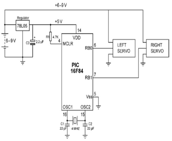
Backward movement
Assuming that the two side wheels are connected to servomotors, the robot moves backward when
- Left wheel rotates clockwise
- Right wheel rotates anti-clockwise
In this project, the left servomotor is connected to port pin RB0 and right servomotor is connected to port pin RB1. The following PicBasic (or PicBasic Pro) code can then be used to move the robot backward:
Backward:
PULSOUT 0, 130 ‘ Left wheel clockwise
PULSOUT 1, 170 ‘ Right wheel anti-clockwise
PAUSE 20 ‘ Wait 20 ms
GOTO Backward ‘ Repeat
For more detail: Servomotor-based mobile robot control