An inverter is a circuit that converts Direct Current (DC) to Alternating Current (AC). A PWM inverter is a type of circuit that uses modified square waves to simulate the effects of Alternating Current (AC), which is suitable for powering most of your household appliances. I say most-of because there generally exist two types of inverters, the first type is the so-called a modified square wave inverter, as the name implies the output is a square wave rather than a sine wave, not a pure sine wave so, if you try to power AC motors or TRIACS, it will cause different problems.
The second type is called a pure sine wave inverter. So it can be used for all kinds of AC appliances without a problem. Learn more about different types of inverter here.
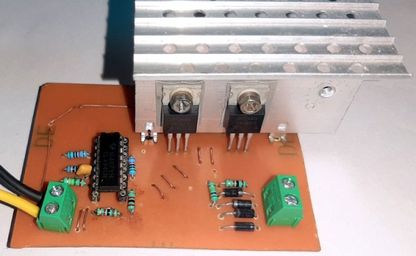
But in my opinion, you should not build an inverter as a DIY project. If you are asking why?, then ride along!, and in this project, I will be building a simple modified square wave PWM inverter circuit by using the popular TL494 chip and explain the pros and cons of such an inverters and at the end, we will see why not to make a modified square wave inverter circuit as a DIY project.
WARNING! This circuit is built and demonstrated for educational purposes only, and it’s absolutely not recommended to build and use this type of circuit for commercial appliances.
CAUTION! If you are making this type of circuit, please be extra careful about high voltage and voltage spikes generated by the non-sinusoidal nature of the input wave.
How does an Inverter Work?
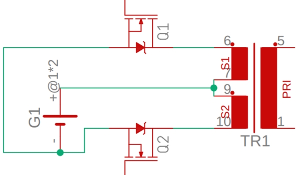
A very basic schematic of the inverter circuit is shown above. A positive voltage is connected to the middle pin of the transformer, which is acting as an input. And the two other pins are connected with the MOSFETs which are acting as switches.
Now if we enable MOSFET Q1, by putting a voltage at the gate terminal the current will flow in one direction of the arrow as shown in the image above. Thus a Magnetic flux will also be induced in the direction of the arrow and the core of the transformer will pass the magnetic flux in the secondary coil, and we will get 220V at the output.
Now, if we disable the MOSFET Q1 and enable the MOSFET Q2, the current will flow in the direction of the arrow shown in the above image, thus reversing the direction of the magnetic flux in the core. Learn more about the working of MOSFET here.
Now, we all know that a transformer work by magnetic flux changes. So, turning both the MOSFETs on and off, one inverted to another and doing that 50 times in a second, will generate a nice oscillating magnetic flux inside the core of the transformer and the changing magnetic flux will induce a voltage in the secondary coil as we know by the faraday’s law. And that is how the basic inverter works.
Inverter IC TL494
Now before building the circuit based upon the TL494 PWM controller, let’s learn how the PWM controller TL494 works.
The TL494 IC has 8 functional blocks, which are shown and described below.
The 5V internal reference regulator output is the REF pin, which is pin-14 of the IC. The reference regulator is there to provide a stable supply for internal circuitry like the pulse-steering flip-flop, oscillator, dead-time control comparator, and PWM comparator. The regulator is also used to drive the error amplifiers which are responsible for controlling the output.
Note! The reference is internally programmed to an initial accuracy of ±5% and maintains stability over an input voltage range of 7V to 40 V. For input voltages less than 7 V, the regulator saturates within 1 V of the input and tracks it.
Source: PWM Inverter Circuit using TL494