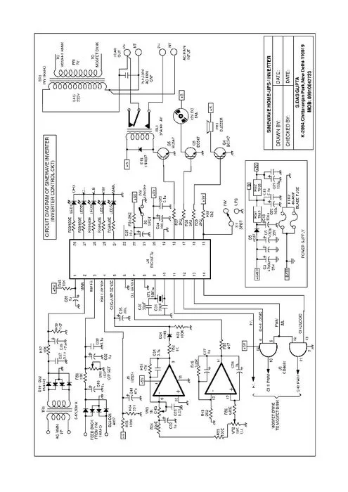
Summary of Pure Sinewave Inverter Using Pic16f72 Without Center Tap Transformer and Without HV Transformer
This article details a reliable pure sine wave inverter project controlled by an 8-bit microcontroller, featuring 230V output, low harmonic distortion, and multiple safety protections like low-battery and overload shutdowns. It includes a MOSFET-based H-bridge circuit with PWM charging and cooling fans. The author provides specific design modifications, such as removing capacitors from IR2110 drivers to prevent overheating, and offers various file downloads for simulation and code implementation using PIC16f72 or PIC16f73 chips.
Parts used in the Pure Sine Wave Inverter:
- 8-Bit Microcontroller (PIC16f72 or PIC16f73)
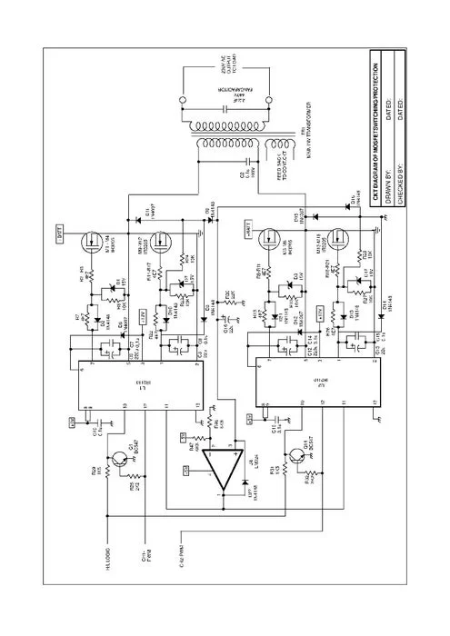
- H-Bridge Inverter Circuit
- MOSFET Switches (IRF3205 or IRF1405)
- IR2110 Driver ICs
- MOSFET based PWM SMPS Charge Controller
- DC Fan for internal cooling
- LED Indicators (or LCD display)
- Resistors (R55 and R54 modified values)
- Capacitor (specifically the 22uF capacitor on IR2110 pins 1 and 2 which must be removed)
finally the most reliable and awaited pure sine wave inverter,it’s here for all members.(don’t hesitate to contact me @ [email protected].
features:
INVERTER O/P VOLT : 230V (+2%)
INV. O/P FREQ : 50Hz
INV. O/P WAVEFORM : SINE WAVE
HARMONIC DISTORTION : <3%
CREST FACTOR : >4:1
INV.EFFICIENCY : 90% for 24V system : >85% for 12V system
AUDIBLE NOISE : <60dB at 1-meter
INV. PROTECTION /
LO-BATTERY SHUT :
OVER LOAD SHUT :
O/P SHORT CKT SHUT:
LO-BATTERY : BEEP START AT 10.5V (BEEP AT EVERY 3-SEC) : INV SHUT DOWN AT 10V (5XBEEP at every 2-SEC)
OVER LOAD : BEEP START AT 120% LOAD (BEEP at every 2-sec) : INV. SHUT DOWN AT 130% LOAD (5XBEEP at every 2-SEC)
LED INDICATION :
INVERTER ON
LOW-BATT – FLASH DUURING L.B ALARM – PERMANENT GLOW DURING CUT
OVER LOAD – FLASH DUURING O.L ALARM- PERMANENT GLOW DURING CUT
CHARGING – FLASH DURING CHARGING – PERMANENT GLOW DURING ABSORPTION
MAIN – MAIN ON
CIRCUIT Features:
8-BIT MICROCONTROLLER BASED CONTROL CIRCUIT
H-BRIDGE INVERTER OPERATION
MOSFET SWITCHING FAULT DETECTION And Shutdown
CHARGING ALGORITHM/
MOSFET based PWM SMPS CHARGE CONTROLLER 5-amp -15-amp
2-STEP CHARGING STEP-1: BOOST MODE (LED FLASH),,,STEP-2: ABSORPTION MODE (LED ON)
DC FAN/
FOR INTERNAL COOLING DURING CHARGING/INV OPERATION
And many more,,,
Step 1: Micro Controller Section
If you want lcd instead of leds,you should replace pic16f72 with pic16f73 and follow lcd wiring pdf all circuit are same.
Step 2: Mosfet Switches Schematic
you can use irf1405(it’s better) instead of irf3205.
Step 3: Part List

replace r55 with :43k and r54 with:12k
so inverter will shutdown at 11v.
THERE IS ONLY ONE PROBLEM I HAVE FACED IT IN THIS DESIGN
YOU SHOULD REMOVE THE (22UF CAPCITOR)(its connected from pin 1 to pin2) FROM EACH IR2110,
IF THIS CAPCITOR IS AVAILABLE YOUR TWO IR2110 WILL BECOME HOT FASTLY AND YOUR MOSFETS WILL
BLOW, BE CAREFUL,JUST REMOVE IT.
Step 4: Files
sinewave.zip is the puresinewave inverter files.
edaboard.zip is proteus simulation files for the puresinewave.
sn73_lcd.zip is for pic16f73(for lcd).
sn73_b.zip is code files for lcd.
sn73_sim.zip is proteus simulation files for the puresinewave with lcd.
keep in mind that the simulation is not 100% actual,this circuit is tested by me and its working.
this inverter isn’t my own design i get from a friend and other files from another sites.
good luck,,,,,,friends.
Attachments
- sinewave.zipDownload
- edaboard.rarDownload
- SN73_LCD.rarDownload
- sn73_lcd_b.rarDownload
- sn73_lcd_Sim.rarDownload
- LCD_WRNG.pdfDownload
Source: Pure Sinewave Inverter Using Pic16f72 Without Center Tap Transformer and Without HV Transformer
- How can I replace LEDs with an LCD display?
You must replace the PIC16f72 with a PIC16f73 and follow the provided LCD wiring PDF while keeping the rest of the circuit the same. - Which MOSFET is better for this design?
The IRF1405 is recommended over the IRF3205 for better performance. - What modification is required to change the low-battery shutdown voltage?
Replace resistor R55 with 43k and R54 with 12k to make the inverter shut down at 11V. - Why should I remove the 22uF capacitor from the IR2110?
Removing the 22uF capacitor connected between pin 1 and pin 2 of each IR2110 prevents the drivers from getting hot and blowing the MOSFETs. - Does the Proteus simulation match the actual circuit perfectly?
No, the simulation is not 100% accurate to the actual circuit, though the physical circuit has been tested and works. - What are the output specifications of this inverter?
The inverter provides 230V (+2%) output at 50Hz with a sine wave waveform and less than 3% harmonic distortion. - How does the charger algorithm operate?
The 2-step charging process includes Boost Mode where the LED flashes and Absorption Mode where the LED glows permanently. - Can I use the files provided for the LCD version in simulation?
Yes, the sn73_sim.zip file contains Proteus simulation files specifically for the pure sine wave inverter with an LCD.