
Summary of PROJECT FINAL WRITE-UP
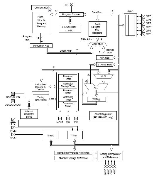
This project implements a Verilog-based Microchip mid-range PIC microcontroller on an Altera DE2 board. Designed to execute pre-determined instructions for computation and I/O control, the system interfaces with a human user, an LCD display, and a ship from the Redhawk Duals project. The architecture mimics a real PIC to allow C compiler usage, requiring simulation of all instructions except CLRWDT, RETFIE, and SLEEP. Input ports are 8-bit bidirectional, controlled via TRIS registers at the bit level.
Parts used in the PIC Microcontroller Implementation:
- Microchip mid-range PIC microcontroller (Verilog version)
- Altera DE2 board
- C compiler
- Human user interface
- LCD display
- Redhawk Duals ship controller
- 8-bit bidirectional IO ports
- TRIS port (direction control register)
Our efforts in this project were to create a version of a Microchip mid-range PIC microcontroller in verilog to run on an Altera DE2 board. It was primarily planned to create a machine that would follow a set of pre-determined instructions and perform computation, interpretation, and control of input and output ports. In order to prove that there was actually a processor under the hood we decided to have the controller interface with (1) a human user, (2) and LCD display, and (3) control a ship from the Redhawk Duals project. There is actually action taken on input from all three sources and control output to the LCD and Basic Ship of the duals project. In an attempt to make writing the code for the controller as easy as possible, the architecture was made to resemble a true PIC so that a C compiler could be used to generate the software interface.
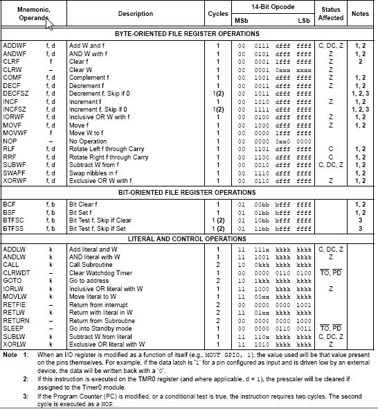
Almost all of the instruction words would be needed to be compatible with the compiler, so after building the verilog PIC every instruction would be needed to be simulated and tested with different values to ensure that the PIC acts as expected. The words not needed are CLRWDT to clear the unimplemented watch-dog timer, RETFIE which is used during returns from interupts which are not implemented, and SLEEP which puts the PIC in low power mode.
The IO ports are 8 bit bidirectional ports that are direction controlled from a TRIS port that determines whether the pins are input or out put, and can control it on a bit by bit basis, or not by requiring the designer to make all 8 bits one direction or another. So they needed to be built bit by bit, and then grouped into groups of 8 for an 8 bit port.
For more detail: PROJECT FINAL WRITE-UP
-
What is the primary goal of this project?
To create a Verilog version of a Microchip mid-range PIC microcontroller running on an Altera DE2 board that performs computation and controls input/output. -
How does the processor interface with external devices?
The controller interfaces with a human user, an LCD display, and a ship from the Redhawk Duals project. -
Why was the architecture designed to resemble a true PIC?
The architecture resembles a true PIC so that a C compiler can be used to generate the software interface easily. -
Which instructions were excluded from the implementation?
The unimplemented instructions are CLRWDT, RETFIE, and SLEEP. -
What is the structure of the IO ports in this design?
The IO ports are 8-bit bidirectional ports where direction is controlled by a TRIS port. -
Can the direction of individual bits be changed?
Yes, the TRIS port allows controlling the direction on a bit-by-bit basis rather than forcing all 8 bits to one direction. -
How was the correctness of the instructions verified?
All instruction words were simulated and tested with different values to ensure the PIC acts as expected.
