Summary of PROGRAMMABLE COMBINATION LOCK CIRCUIT PIC16F84
This article describes a programmable combination lock circuit using the PIC16F84 microcontroller. The system features a 4x3 keypad for password entry, LED indicators, and a buzzer for alerts. A relay controls the unlock mechanism when the correct code (default 1234) is entered. Users can change the password via a specific sequence involving an asterisk and hash key. Simulation files and hex code are available for download.
Parts used in the Programmable Combination Lock Circuit:
- PIC16F84 Microcontroller
- 4x3 Matrix Keypad
- LED Indicators
- Buzzer
- Relay
Prepared by: F. San – 1 relay control circuit pic-16f84 is based on the keypad’s LED indicators and buzzer alert source. Bass. Hex code and simulation files have isis proteus. Thanks to the people who contributed to prepare. 4… Electronics Projects, Programmable Combination Lock Circuit PIC16F84 “microchip projects, microcontroller projects, pic16f84 projects,
Prepared by: F. San – 1 relay control circuit pic-16f84 is based on the keypad’s LED indicators and buzzer alert source. Bass. Hex code and simulation files have isis proteus. Thanks to the people who contributed to prepare.
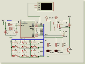
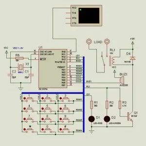
4 × 3 matrix form lock password is entered via a keypad connected. As soon as the circuit programmable lock password is 1234. Activate the relay output that is keyed to unlock and then # 1234 is printed. If the password error relay is energized. To change the current password, for example, in 1961: 1234 * 1961 # 1961 # to be monitored as a key sequence. Changing the password fails, the old password will remain valid.
PIC16F84 COMBINATION LOCK CIRCUIT SCHEMATIC
Combination Lock code and circuit files:
FILE DOWNLOAD LINK LIST (in TXT format): LINKS-9183.zip
Source: PROGRAMMABLE COMBINATION LOCK CIRCUIT PIC16F84
- What is the default password for the lock?
The default programmable lock password is 1234. - How do I change the current password?
To change the password, enter the old password followed by *, the new password, and #. - What happens if the password entry is incorrect?
If the password is wrong, the relay is energized as an error alert. - Which microcontroller is used in this project?
The circuit uses the PIC16F84 microcontroller. - Can I simulate this circuit before building it?
Yes, ISIS Proteus simulation files are provided with the project. - What input method is used to enter the password?
A 4x3 matrix form keypad is connected to enter the password. - What indicates a successful unlock attempt?
The relay output activates to unlock the system upon correct entry.