Background
Most multimeters can measure frequency, but they are not sensitive and the max frequency is not always so high.
The same problem can be found with older frequency counters.
This project will describe a prescaler which will work up to 2.5GHz and with very high input sensitivity.
The prescaler will divide the input frequency with either 1000 or 10.000.
The divided output signal is 0/5 volt and can be connected to your instrument as it is.
The divider ration is set by a jumper (switch).
A PIC 16F84 handle all communication to the prescaler.
Example:
I have a frequency of 100MHz.
I set the divider to 1000.
The output signal from the divider will now be 100e6/1000 = 100.000Hz.
My multimeter show me 100.0kHz
If I now change the divider to 10.000, the output will be 100e6/10000 = 10.000Hz.
My multimeter show me 10.0kHz
Conclusion:
Even if the prefix (kHz) is not correct on my multimeter, I will know that the measurement is MHz and I can see the reading.
A simple and easy way to measure frequency.
Hardware and schematic
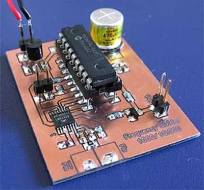
The main part of this project is the PIC16F84 and a prescaler LMX2322.
The input of the LMX2322 is symmetrically at pin 7 and 8.
The input impedance is about 100 ohm and with R7 you form an input impedance of 50 ohm.
Transistor Q1 forms a buffer for the output frequency which is the divided signal.
The output is TTL level and can be directly connected to any instrument.
SW1 is the switch that set the divider ration.
- If SW1 = Off the divider ration is 1000.
- If SW1 = On the divider ration is 10.000.
PCB
| div1000.pdf | PCB file for Poor man’s counter (pdf). |
Above you can download a (pdf) filer which is the black PCB.
The PCB is mirrored because the printed side should be faced down the board during UV exposure.
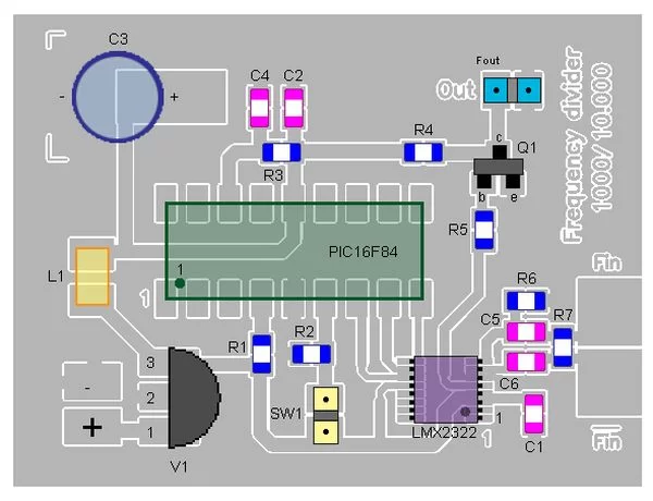
To the right you will find a pic showing the assembly of all components on the same board.
This is how the real board should look when you are going to solder the components.
It is a board made for surface mounted components, so the copper is on the top layer.
Grey area is coppar and each component is draw in different colours all to make it easy to identify for you.
The scale of the pdf is 1:1 and the picture at right is magnified with 4 times.
Click on the picture to enlarge it.
For more detail: Poor man’s counter using PIC16F84 microcontroller


