Calculator using PIC24FJ64GA006 with Proteus Simulation

Summary of Calculator using PIC24FJ64GA006 with Proteus Simulation


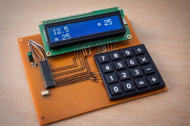
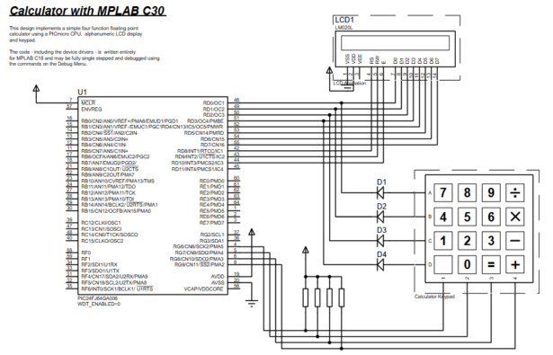
Building a floating-point calculator using a PIC24FJ64GA006 microcontroller with a 4×4 keypad input and a 20×2 (LM020L) LCD display, developed in Embedded C (MPLAB C30) and testable in Proteus VSM. The system scans keypad input, stores numeric operands, performs arithmetic (including division error handling), formats results, and shows them on the LCD, providing a learning platform for keypad scanning, LCD interfacing, and microcontroller-based arithmetic processing.

Parts used in the PIC24 Calculator with Proteus Simulation:

  • PIC24FJ64GA006 Microcontroller
  • 20×2 Alphanumeric LCD (LM020L)
  • 4×4 Matrix Keypad
  • Pull-up Resistors
  • Diodes for keypad isolation
  • Power supply
  • Proteus VSM simulation environment

Introduction

The PIC24 Calculator Proteus Simulation project demonstrates how a microcontroller can be used to build a simple digital calculator using a keypad and LCD display. In this microcontroller project, the PIC24FJ64GA006 performs arithmetic operations based on user input from a 4×4 keypad and shows the results on an LCD screen.

Developed using the MPLAB C30 compiler and tested through Proteus simulation, the PIC24 Calculator Proteus Simulation helps students and engineers understand keypad interfacing, LCD control, and real-time arithmetic processing. It is a useful practical example for learning embedded systems, microcontroller programming, and DIY electronics design.

PIC24 keypad LCD calculator prototype
Illustrative View of the Concept.

How the Project Works (Overview)

The calculator system uses a 4×4 matrix keypad as the input interface. When a user presses a key, the PIC24 microcontroller scans the keypad rows and columns to detect which button is pressed.

The detected key is interpreted either as a numeric digit, decimal point, or arithmetic operator (+, −, ×, ÷). The program stores the entered numbers and performs floating-point calculations using internal variables.

The result of the operation is formatted and displayed on the LM020L alphanumeric LCD display connected to the microcontroller.

The entire system runs in a continuous loop where it:

  1. Reads keypad input

  2. Determines whether the input is a digit or operator

  3. Stores and evaluates numeric values

  4. Performs arithmetic operations

  5. Displays results on the LCD

Workflow Explanation

The project architecture can be explained through the following logical flow:

User Input → Keypad Scanner → PIC24 Microcontroller → Arithmetic Processing → LCD Display

Step-by-Step Workflow

  1. Keypad Input

    • A 4×4 matrix keypad provides digits and operator inputs.

  2. Keypad Scanning

    • The microcontroller scans rows and columns to detect which key is pressed.

  3. Data Processing

    • Numeric input is stored as a floating-point value.

    • Operators trigger calculation routines.

  4. Arithmetic Evaluation

    • Operations like addition, subtraction, multiplication, and division are performed.

  5. Display Output

    • Results are formatted and shown on the LCD screen.

Key Features

  • Floating-point arithmetic calculations

  • 4×4 matrix keypad input system

  • LCD output display for results

  • Division error handling

  • Decimal number support

  • Real-time input processing

  • Embedded C implementation using MPLAB C30

  • Fully testable in Proteus VSM simulation

Components Used

The following components are identified from the schematic and firmware:

  • PIC24FJ64GA006 Microcontroller

  • 20×2 Alphanumeric LCD (LM020L)

  • 4×4 Matrix Keypad

  • Pull-up Resistors

  • Diodes for keypad isolation

  • Power supply

  • Proteus VSM simulation environment

Explanation of Code

The firmware is written in Embedded C using MPLAB C30 and is divided into several functional modules.

1. LCD Driver Module

This module initializes and controls the LCD display. It sends commands and characters to the LCD through the microcontroller’s I/O ports.

Functions include:

  • lcd_init() – Initializes the LCD display

  • wrcmd() – Sends control commands

  • wrdata() – Writes characters to LCD

  • clearscreen() – Clears the display

These routines manage the LCD interface and ensure proper communication with the display hardware.

2. Keypad Scanning Module

This module scans the 4×4 matrix keypad by driving rows and reading columns. When a key press is detected, it returns the corresponding ASCII value.

Example keypad mapping:

7 8 9 /
4 5 6 *
1 2 3 –
. 0 = +

The keypad scanning logic continuously checks each row and column to determine which key is pressed.

3. Calculator Logic Module

The main calculator logic performs arithmetic operations using floating-point values.

Core variables:

  • lvalue – left operand

  • rvalue – right operand

  • lastop – last operator pressed

The program evaluates operations using a switch statement that performs addition, subtraction, multiplication, or division.

Division by zero is detected and an ERROR message is displayed on the LCD.

4. Number Formatting

The program converts floating-point results into readable characters before displaying them on the LCD.

This formatting routine ensures that numbers appear correctly within the LCD display limits.

PIC24 calculator keypad LCD schematic diagram

Source Code

/******************************************************************************            
************                 LABCENTER ELECTRONICS                  ************            
************           Proteus VSM Sample Design Code               ************            
************                   MPLAB C30 'C' Calculator             ************            
*******************************************************************************/       

#include "p24FJ64GA006.h"
#include "calc.h"
#include "stddef.h"
#include "math.h"
#include "stdlib.h"
#include "string.h"

_CONFIG1(FWDTEN_OFF);
_CONFIG2(FNOSC_FRC&POSCMOD_NONE);

Proteus Simulation

The Proteus VSM simulation demonstrates how the calculator behaves in real time.

Simulation behavior:

  1. Press digits on the keypad.

  2. The number appears on the LCD display.

  3. Press an operator (+, −, ×, ÷).

  4. Enter the second number.

  5. Press = to calculate the result.

The LCD instantly displays the computed value, allowing developers to verify the firmware functionality without physical hardware.

Conclusion

The PIC24 Calculator with Proteus Simulation is a practical embedded systems project that demonstrates keypad interfacing, LCD communication, and arithmetic processing using a microcontroller. It is an excellent learning example for students and engineers exploring microcontroller projects, firmware development, and Proteus-based circuit simulation.

By combining embedded C programming with Proteus VSM, this project provides a hands-on approach to understanding how digital systems interact with user input and display devices in real-world electronics applications.

Quick Solutions to Questions related to PIC24 Calculator with Proteus Simulation:

  • How does the calculator detect which keypad key is pressed?
    The microcontroller scans keypad rows and columns by driving rows and reading columns to detect the pressed key.
  • Can the project handle decimal numbers?
    Yes, the project supports decimal number input and floating-point calculations.
  • What arithmetic operations are supported?
    The calculator supports addition, subtraction, multiplication, and division.
  • How is division by zero handled?
    The program detects division by zero and displays an ERROR message on the LCD.
  • What compiler and language are used to develop the firmware?
    The firmware is written in Embedded C using the MPLAB C30 compiler.
  • How are results shown to the user?
    Results are formatted and displayed on the 20×2 LM020L alphanumeric LCD.
  • Can the design be tested without physical hardware?
    Yes, the design is fully testable in the Proteus VSM simulation environment.
  • What modules divide the firmware functionality?
    The firmware is divided into LCD driver, keypad scanning, calculator logic, and number formatting modules.

About The Author

Ibrar Ayyub

I am an experienced technical writer holding a Master's degree in computer science from BZU Multan, Pakistan University. With a background spanning various industries, particularly in home automation and engineering, I have honed my skills in crafting clear and concise content. Proficient in leveraging infographics and diagrams, I strive to simplify complex concepts for readers. My strength lies in thorough research and presenting information in a structured and logical format.

Follow Us:
LinkedinTwitter