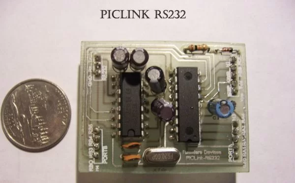
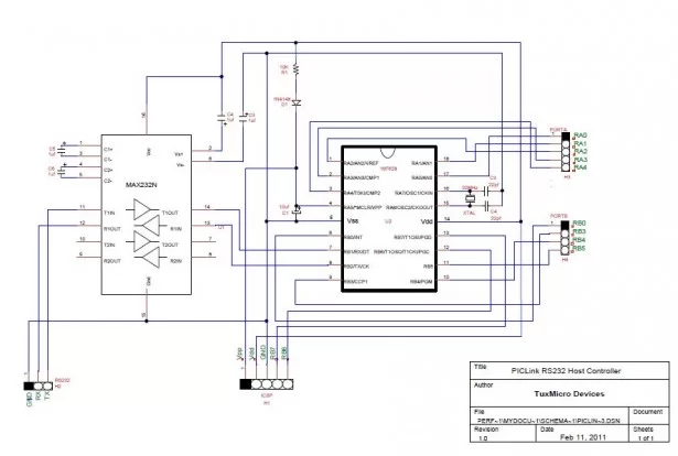
PicLink RS232 low cost development controller with ADC
PICLink RS232 Embedded Controller
The PICLink RS232 controller module affords any microcontroller enthusiast an
easy to construct mini-microcontroller module. This embedded microcontroller is
ICSP (in circuit serial) programmable and provides separate PORTA, PORTB,
RS232 I/O ports, 4 Channel Analog to Digital converter as well as an integrated ICSP port to implement in circuit programming and debugging. On board host RS232 USART may be used to interface with a PC (USB to RS232) or any other serial communications device like our 2.4 GHz Wi-Fi or 915MHz wireless modules. In this instructable you will need to manufacture a double sided circuit board (circuit board dimensions are given below), assemble the board with the necessary components (see components list) and then program the controller with LES firmware version 1.1. For this you will need an ICSP programmer such as the USBPIC Programmer or the PICKit 2 which is what I currently use as an engineer and firmware developer. I would recommend for those whom are serious about embedded device engineering spending the $30 dollars (USD) for the PICKit. The PICKit2 LogicTool will serve to be a great development tool when developing embedded control devices.
LES 1.1 Firmware
LES-1.0 (version 1.0) is a miniaturized embedded framework written in
C currently for PIC micro-controllers which supports basic input/output, memory
and RS232 asynchronous communications. Because of its small foot print the
entire system can fit into 1K (1024 Bytes) of program memory. In addition LES
greatly simplifies bit level control of IO ports through macros like BIT_SET,
BIT_CLEAR, BIT_IS_SET and BIT_COMP. Port register control
is achieved through PORTx macros which reduce bit level TRISx calls this saving
critical program memory space.
LES 1.1 Firmware was developed using Eclipse SDCC and GPUTILS. The PICLink (LES) build environment is simple to set up and requires no proprietary licensed software. SDCC and GPUTILS are opensource development tools published under the GNU Public License agreement and are free for download and use. As soon as I get a chance I will update the LES article with download and SDCC install instructions.
URF 1000 Sonar
The PICLink RS232 embedded controller was developed to calculate distance and transmit telemetric data to host terminal when interfaced with TuxMicro’s URF 1000 Series Ultrasonic Sonar Range Finder DSM module.
Features
· Supply Voltage – 5.0 to 5.5 VDC H1-2
· Supply Current – 10 mA typ
· ICSP (In-Circuit Serial Programmable)
Supports Microchip device debugging via H1
· 20 MHz Crystal controlled SBC
· 11 bi-directional I/O Pins
· 4 channel ADC (PORTA)
· Dedicated RS232 USART Port 120 kbit/s
· RS232 speeds 1200 to 155200 bit/s
· 128 Bytes EEPROM
· 224 Bytes SRAM
· 2 K Bytes program memory (1k when running LES)
· LES firmware version 1.1
Module Dimensions
52.5 mm L x 41 mm W x 1.6mm H (2.06in x 1.61 in x 0.63 in)
PicLink Mother Board fabrication – Bottom Layer
Circuit Board fabrication materials using DirectEtch
Toner Transfer pape r, environmentally friendly etchant (2oz hydrogen peroxide mixed with 1oz muriatic acid) a plastic well of water (sandwich container or 8″ brownie pan), paper towel, plastic gloves, sandwich container (found at Dollar Tree two for one dollar), fine steel wool and a small can of Acetone to remove the toner foil “resist” image from the board after etching. You will need either a laser printer or copier to transfer copies of the circuit templates to the toner transfer paper. Also it would be extra easy is you could gain access to a laminator such as a GBC Creative Laminator. The GBC Creative Laminator makes producing double sided circuit boards very easy since both sides of the circuit board is heated evenly during the toner transfer to circuit board.
1/2oz Copper, .032″ thick Double Sided Copper clad circuit board is recommended to make this product since it can be cut with a pair of heavy duty utility scissors.
Cut a piece of double sided board to 55mm x 45mm then clean both surfaces with Acetone and buff with fine steel wool until a mirror finish is obtained. For best results after buffing clean sides with Denatured alcohol or Marine stove fuel.
PicLink Mother Board fabrication – Top Layer
Toner Transfer Direct-etch
Reproduce image art of circuit board onto a single sheet of 8.5 x 11″ toner transfer paper shiny side to to image. Be sure to handle the materials with plastic gloves on since the oils in one skin can distort the image quality.
How to make Direct Etch Transfer paper
Toner Transfer paper is business card stock with a layer of Dextrin (cooked corn starch). Dextrin can be made from ARGO Corn Starch by sprinkling a thin layer of corn starch on a cookie sheet an baking in an oven at 350° F for 120 minutes. During the baking cycle it is necessary to stir the starch at 30 minute intervals to help insure even drying. After baking the cornstarch the dried powder (Dextrin) can be mixed with water to make paste (approximately 1.5 tablespoons of powder to one cup of water). Kiwi Water repellent (silicone spray) is then applied to a sheet of the paper stock dried and then coated with a thin layer of Dextrin paste. Once the paste dries you have homemade Toner Transfer Paper ready to make circuit boards.
After circuit board is cut, polished, washed with solvent it is ready for transfer of image art.
Once art is copied onto a sheet of Toner Transfer paper the art is then cut out in squares so that the target symbols on both top and bottom layers will match up when facing each other. Remember your image must be on the shiny side of the transfer paper so that when both top and bottom images face each other the circuit trace donuts will line up. This is necessary to check since the copper clad board will actually be placed between these two sheets and taped with Scotch tape on one end in order to help prevent slippage. Keeping this in mind lay out the squares of art as to make a laminator pouch from them by taping one end together while insuring the two images and target symbols mate evenly.


