Summary of PIC’ing the MAX5581: Interfacing a PIC Microcontroller with the MAX5581 Fast-Settling DAC
The article details an application circuit interfacing the MAX5581 12-bit DAC with a PIC18F442 microcontroller using SPI. It covers hardware setup, including ground plane separation and firmware initialization to generate a square wave for testing settling time.
Parts used in PIC'ing the MAX5581:
- MAX5581 DAC
- PIC18F442 Microcontroller
- MAX6126 Voltage Reference
- TDK MMZ1608B601C Ferrite Bead
- Pushbutton Switches (Two)
- Gain Setting Resistors
- MPLAB IDE Version 6.10.0.0 Assembler
MAX5581 Overview
The MAX5581 is a 12-bit, fast-settling DAC featuring a 3-wire SPI™ serial interface. The MAX5581’s interface can support SPI up to 20MHz with a maximum settling time of 3µs. This application note presents an application circuit and all the firmware required to interface the fastest line of PIC microcontrollers (PIC18F core) to the MAX5581 DAC. The example assembly program was written specifically for the PIC18F442 using the free assembler provided in MPLAB IDE version 6.10.0.0.
Hardware Overview
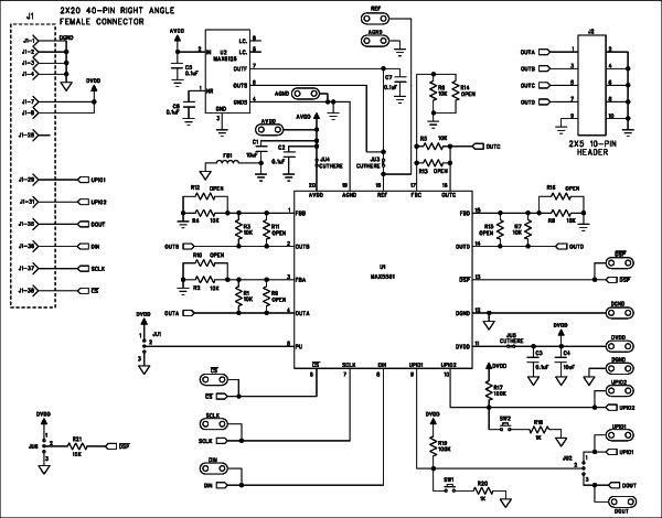
The application circuit discussed here uses the MAX5581 Evaluation (EV) Kit, which consists of the MAX5581, an ultra-high-precision voltage reference (MAX6126), two pushbutton switches, gain setting resistors, and a proven PCB layout. The PIC18F442 is not present on the MAX5581EVKIT board, but was added to the system to complete the application schematic shown in Figure 1. The /CS\, SCLK, DIN, and DOUT pads on the MAX5581EVKIT allow an easy connection for the SPI serial interface.
Analog and Digital Ground Planes
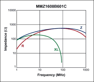
It is good practice to separate the analog and digital ground planes, as shown in Figure 2. Use a ferrite bead, such as the TDK MMZ1608B601C, to connect both ground planes together through a ferrite bead. This prevents the microcontroller’s system clock and its harmonics from feeding into the analog ground. Knowing that the PIC18F442’s system clock is 40MHz, the MMZ1608B601C was chosen for its specific impedance vs. frequency characteristics. Figure 3 shows the impedance versus frequency curve for the MMZ1608B601C.
Firmware Overview
The example assembly program shown in Listing 1 initializes the MAX5581 using the PIC18F442’s internal MSSP SPI peripheral. The PIC18F442’s 40MHz system clock allows the MSSP to provide an SPI clock (SCLK) up to 10MHz. Table 1 shows the only configuration word required after power. Once the MAX5581 is initialized, the program constantly loads the DAC output registers with zero scale followed by full scale, as shown in Table 2. This constant loop results in a square wave, shown in Figure 4, which demonstrates the fast settling time of the MAX5581.
Listing 1.asm
;******************************************************************************
;
;    Filename:		Listing 1 (Absolute Code Version)
;    Date:    		2/25/05
;    File Version:  	1.0
;
;    Author:        	Ted Salazar
;    Company:       	Maxim
;
;******************************************************************************
;
;	Program Description:
;
;	This program interfaces the internal SPI MSSP
;	(Peripheral) of the PIC18F442 to the MAX5581 SPI
;	Quad DAC. The program initializes the MAX5581
;	and dynamically generates a 50% duty cycle square
;	wave with a frequency of 80KHz.
;
;
;******************************************************************************
;
; History:
; 2/25/05: Tested SPI DAC format
; 2/25/05: Initialized MAX5591
; 12/14/04: Cleared tcount timer in HWSPI_W_spidata_W
;******************************************************************************
;******************************************************************************


;
;******************************************************************************
;
;    Files required:         P18F442.INC
;
;******************************************************************************
	radix hex               ;Default to HEX
	LIST P=18F442, F=INHX32	;Directive to define processor and file format
	#include 	;Microchip's Include File
;******************************************************************************
;******************************************************************************
xmit    equ		06 		; Asynchronous TX is at C6
;
;******************************************************************************
;Configuration bits
; The __CONFIG directive defines configuration data within the .ASM file.
; The labels following the directive are defined in the P18F442.INC file.
; The PIC18FXX2 Data Sheet explains the functions of the configuration bits.
; Change the following lines to suit your application.

;T	__CONFIG	_CONFIG1H, _OSCS_OFF_1H & _RCIO_OSC_1H
;T	__CONFIG	_CONFIG2L, _BOR_ON_2L & _BORV_20_2L & _PWRT_OFF_2L
;T	__CONFIG	_CONFIG2H, _WDT_ON_2H & _WDTPS_128_2H
;T	__CONFIG	_CONFIG3H, _CCP2MX_ON_3H
;T	__CONFIG	_CONFIG4L, _STVR_ON_4L & _LVP_OFF_4L & _DEBUG_OFF_4L
;T	__CONFIG	_CONFIG5L, _CP0_OFF_5L & _CP1_OFF_5L & _CP2_OFF_5L & _CP3_OFF_5L
;T	__CONFIG	_CONFIG5H, _CPB_ON_5H & _CPD_OFF_5H
;T	__CONFIG	_CONFIG6L, _WRT0_OFF_6L & _WRT1_OFF_6L & _WRT2_OFF_6L & _WRT3_OFF_6L
;T	__CONFIG	_CONFIG6H, _WRTC_OFF_6H & _WRTB_OFF_6H & _WRTD_OFF_6H
;T	__CONFIG	_CONFIG7L, _EBTR0_OFF_7L & _EBTR1_OFF_7L & _EBTR2_OFF_7L & _EBTR3_OFF_7L
;T	__CONFIG	_CONFIG7H, _EBTRB_OFF_7H

;******************************************************************************
;Variable definitions
; These variables are only needed if low priority interrupts are used.
; More variables may be needed to store other special function registers used
; in the interrupt routines.
		CBLOCK	0x080
		WREG_TEMP	;variable used for context saving
		STATUS_TEMP	;variable used for context saving
		BSR_TEMP	;variable used for context saving
		;
		ENDC

		CBLOCK	0x000
		EXAMPLE	;example of a variable in access RAM
		;
		temp    	;
		temp2
		;
		xmtreg  	;
		cntrb   	;
		cntra   	;
		bitctr  	;

		tcount	;
		speedLbyte	;T Being used in HWSPI_speed
		;
		ENDC
;******************************************************************************
;Reset vector
; This code will start executing when a reset occurs.

		ORG	0x0000

		goto	Main	;go to start of main code

;******************************************************************************
;High priority interrupt vector
; This code will start executing when a high priority interrupt occurs or
; when any interrupt occurs if interrupt priorities are not enabled.

		ORG	0x0008

		bra	HighInt	;go to high priority interrupt routine

;******************************************************************************
;Low priority interrupt vector and routine
; This code will start executing when a low priority interrupt occurs.
; This code can be removed if low priority interrupts are not used.

		ORG	0x0018

		movff	STATUS,STATUS_TEMP	;save STATUS register
		movff	WREG,WREG_TEMP		;save working register
		movff	BSR,BSR_TEMP		;save BSR register

;	*** low priority interrupt code goes here ***


		movff	BSR_TEMP,BSR		;restore BSR register
		movff	WREG_TEMP,WREG		;restore working register
		movff	STATUS_TEMP,STATUS	;restore STATUS register
		retfie

;******************************************************************************
;High priority interrupt routine
; The high priority interrupt code is placed here to avoid conflicting with
; the low priority interrupt vector.

HighInt:

;	*** high priority interrupt code goes here ***
CBLOCK 0x080
WREG_TEMP ;variable used for context saving
STATUS_TEMP ;variable used for context saving
BSR_TEMP ;variable used for context saving
;
ENDC
CBLOCK 0x000
EXAMPLE ;example of a variable in access RAM
;
temp ;
temp2
;
xmtreg ;
cntrb ;
cntra ;
bitctr ;
tcount ;
speedLbyte ;T Being used in HWSPI_speed
;
ENDC
;******************************************************************************
;Reset vector
; This code will start executing when a reset occurs.
ORG 0x0000
goto Main ;go to start of main code
;******************************************************************************
;High priority interrupt vector
; This code will start executing when a high priority interrupt occurs or
; when any interrupt occurs if interrupt priorities are not enabled.
ORG 0x0008
bra HighInt ;go to high priority interrupt routine
;******************************************************************************
;Low priority interrupt vector and routine
; This code will start executing when a low priority interrupt occurs.
; This code can be removed if low priority interrupts are not used.
ORG 0x0018
movff STATUS,STATUS_TEMP ;save STATUS register
movff WREG,WREG_TEMP ;save working register
movff BSR,BSR_TEMP ;save BSR register
; *** low priority interrupt code goes here ***
movff BSR_TEMP,BSR ;restore BSR register
movff WREG_TEMP,WREG ;restore working register
movff STATUS_TEMP,STATUS ;restore STATUS register
retfie
;******************************************************************************
;High priority interrupt routine
; The high priority interrupt code is placed here to avoid conflicting with
; the low priority interrupt vector.
HighInt:
; *** high priority interrupt code goes here ***
For more detail: PIC’ing the MAX5581: Interfacing a PIC Microcontroller with the MAX5581 Fast-Settling DAC
-
What is the primary function of the MAX5581 described in the article?
The MAX5581 is a 12-bit, fast-settling DAC featuring a 3-wire SPI serial interface that supports speeds up to 20MHz. -
Which microcontroller core is used to interface with the MAX5581 in this project?
The project uses the PIC18F442, which belongs to the fastest line of PIC microcontrollers based on the PIC18F core. -
How are the analog and digital ground planes connected in the circuit design?
The ground planes are connected together through a ferrite bead, specifically the TDK MMZ1608B601C, to prevent system clock harmonics from entering the analog ground. -
What specific frequency does the ferrite bead MMZ1608B601C target for impedance matching?
The bead was chosen because the PIC18F442 operates at a 40MHz system clock, and the bead has specific impedance versus frequency characteristics suitable for this. -
What peripheral of the PIC18F442 is utilized to initialize the MAX5581?
The program initializes the MAX5581 using the internal MSSP SPI peripheral of the PIC18F442. -
What waveform is generated by the example assembly program to demonstrate performance?
The program generates a 50% duty cycle square wave with a frequency of 80KHz by constantly loading the DAC registers with zero scale followed by full scale. -
Is the PIC18F442 included on the standard MAX5581 Evaluation Kit board?
No, the PIC18F442 is not present on the MAX5581EVKIT board but was added to the system to complete the application schematic. -
What software tool and version were used to write the example assembly program?
The program was written using the free assembler provided in MPLAB IDE version 6.10.0.0.