Summary of PIC18F4580 USB ANALYZER CIRCUIT LCD 4-CHANNEL
This article describes a 4-channel USB logic analyzer project built around the PIC18F4580 microcontroller. The system features a 128×64 graphic LCD for display and supports sampling frequencies of 200Hz and 2MHz. It includes a charging circuit for an integrated 9V battery, operates on 12V or 9V power, and provides downloadable assembly source code, hex files, and PCB designs.
Parts used in the PIC18F4580 USB Analyzer Circuit:
- PIC18F4580 microcontroller
- 128 × 64 graphic LCD (GLCD to DEM128064-FGH-PW)
- Assembly source software
- Hex file
- PCBs
- 4 pcs channels
- 12volt supply
- 9V battery
- Charging section
Pic18f4580 microcontroller circuit based on logic analyzer display 128 × 64 graphic LCD (GLCD to DEM128064-FGH-PW) used. Prepared by the assembly source software. Asm,. Hex file and PCB’s. Logic analyzer circuit characteristics; Sampling Frequency: 200Hz, 2MHz Number of Channels:… Electronics Projects, PIC18F4580 USB Analyzer Circuit LCD 4-Channel “microchip projects, microcontroller projects,
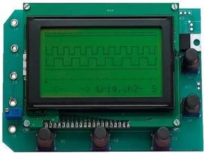
Pic18f4580 microcontroller circuit based on logic analyzer display 128 × 64 graphic LCD (GLCD to DEM128064-FGH-PW) used. Prepared by the assembly source software. Asm,. Hex file and PCB’s.
LOGIC ANALYZER CIRCUIT CHARACTERISTICS;
Sampling Frequency: 200Hz, 2MHz
Number of Channels: 4 pcs
Memory per channel in 1024
Trigger levels (Trigger Level): + And on and on-and
Supply: 12volt + 9V battery
9-volt battery used in the circuit will be charged automatically on the circuit’s charging section
Source: http://www.rlocman.ru/shem/schematics.html?di=64291 USB Analyzer Circuit files alternative link :
FILE DOWNLOAD LINK LIST (in TXT format): LINKS-10317.zip
Source: PIC18F4580 USB ANALYZER CIRCUIT LCD 4-CHANNEL
- What is the sampling frequency of this logic analyzer?
The sampling frequencies are 200Hz and 2MHz. - How many channels does the circuit support?
The circuit has 4 channels. - Can the 9-volt battery be charged automatically?
Yes, the 9-volt battery will be charged automatically on the circuit's charging section. - What power supplies can be used for the circuit?
The circuit uses a 12volt supply and a 9V battery. - Which microcontroller is used in this project?
The project uses the Pic18f4580 microcontroller. - What type of display is used in the circuit?
A 128 × 64 graphic LCD is used. - Is assembly source software provided for the project?
Yes, assembly source software is prepared for the project. - Are PCB designs available for download?
Yes, PCBs along with hex files and source code are available for download.