PIC18 and MAX6675 Thermometer using PIC18F452 with Proteus Simulation

Summary of PIC18 and MAX6675 Thermometer using PIC18F452 with Proteus Simulation


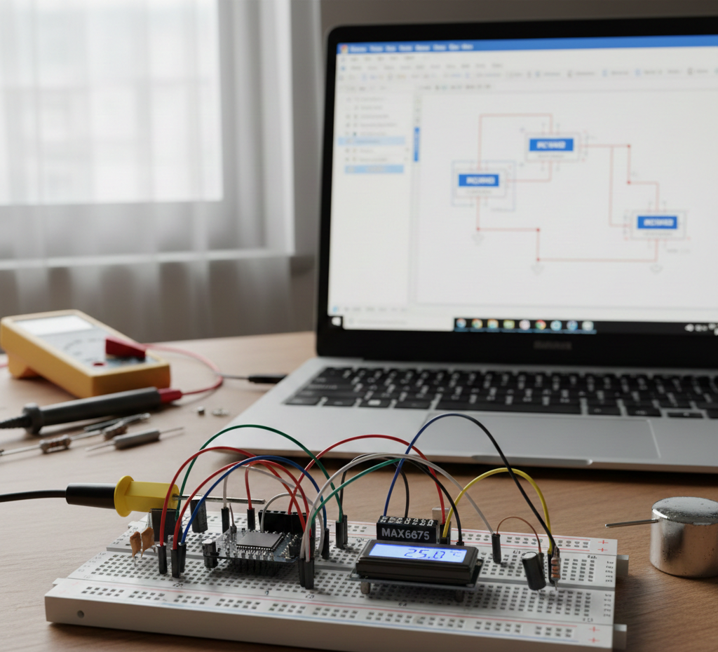
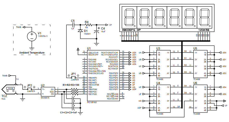
This project implements a high-temperature digital thermometer using a PIC18F452 microcontroller and a MAX6675 K-type thermocouple interface. It reads thermocouple data via the MAX6675, converts and formats temperature into BCD, and displays values on a multiplexed six-digit seven-segment display using Timer0-driven interrupts. The system detects thermocouple disconnection and was developed and validated entirely in Proteus using the SourceBoost C compiler.

Parts used in the PIC18 and MAX6675 Thermometer:

  • PIC18F452 microcontroller
  • MAX6675 thermocouple-to-digital converter
  • K-type thermocouple
  • Six-digit seven-segment display
  • NPN transistor drivers
  • Resistors (for segment limiting and pull-ups)
  • Capacitors (filtering and timing)
  • External clock source (4 MHz)

Introduction

This microcontroller project demonstrates a high-temperature digital thermometer built around the PIC18F452 and the MAX6675 K-type thermocouple interface.
Designed and tested entirely using Proteus simulation, the project shows how embedded systems can accurately measure and display temperature values in real time.
It combines sensor interfacing, display multiplexing, and interrupt-driven firmware into one practical electronics application.
Using the SourceBoost C Compiler, this project is ideal for learning temperature sensing, SPI-based peripherals, and seven-segment display control.
It’s a solid example of a real-world DIY electronics system with clean hardware-software integration.

Breadboard MAX6675 thermometer setup.
Illustrative View of the Concept.

How the Project Works (Overview)

The PIC18F452 communicates with the MAX6675 to read temperature data from a K-type thermocouple.
The MAX6675 converts the thermocouple signal into a digital temperature value, which is processed by the microcontroller.
The firmware formats this value and displays it on a multiplexed six-digit seven-segment display.
Timer0 interrupts handle display refreshing to ensure smooth, flicker-free output.
The system also detects thermocouple disconnection and displays an error message.

Block Diagram / Workflow Explanation

  1. Thermocouple (K-Type) senses high temperature

  2. MAX6675 converts analog thermocouple data into digital temperature values

  3. PIC18F452 reads temperature via MAX6675 interface

  4. Firmware formats temperature into BCD

  5. Timer0 interrupt drives display multiplexing

  6. Seven-segment displays show temperature in °C

  7. Error detection triggers an “open thermocouple” message when needed

Key Features

  • High-temperature measurement using K-type thermocouple

  • Digital temperature conversion via MAX6675

  • Interrupt-driven seven-segment multiplexing

  • Thermocouple open-circuit detection

  • Stable display refresh using Timer0

  • Fully testable in Proteus simulation

  • Uses SourceBoost C for compact firmware

Components Used

  • PIC18F452 microcontroller

  • MAX6675 thermocouple-to-digital converter

  • K-type thermocouple

  • Six-digit seven-segment display

  • NPN transistor drivers

  • Resistors and capacitors (filtering & timing)

  • External clock source (4 MHz)

Applications

  • Industrial temperature monitoring

  • Furnace and oven temperature measurement

  • Laboratory thermal experiments

  • Embedded systems learning projects

  • High-temperature data logging front-ends

  • Thermocouple interface demonstrations

Explanation of the Code (High-Level)

The firmware initializes Timer0 to generate periodic interrupts used for display multiplexing.
During each interrupt, one digit of the seven-segment display is activated while segment data is updated.
The MAX6675 is read at fixed intervals, with interrupts temporarily disabled to avoid data corruption.
Temperature data is converted into BCD format for display.
If the thermocouple is disconnected, the firmware displays an error message instead of numeric data.

Source Code

Download
#include 
#include "max6675lib.h"

#pragma DATA _CONFIG2H, _WDT_OFF_2H
#pragma CLOCK_FREQ 4000000


bit disoff_tris   @ TRISB.0;
bit disoff_out    @ PORTB.0;

static char tbuff[4];
static char digit = 0;
static int  interrupt_timer = 0;

Proteus Simulation

In Proteus, the MAX6675 and PIC18F452 operate exactly as real hardware.
The seven-segment display updates smoothly through interrupt-driven multiplexing.
Temperature changes at the thermocouple input immediately reflect on the display.
Open-thermocouple conditions trigger the error message automatically.

(FAQs)

1. Why does the display flicker in Proteus?

Check Timer0 configuration and interrupt frequency.

2. Can I use a different PIC18 microcontroller?

Yes, but pin mapping and configuration bits must be updated.

3. Why disable interrupts while reading MAX6675?

To avoid SPI timing conflicts during temperature conversion.

4. Does this work without real hardware?

Yes, the project is fully functional in Proteus simulation.

5. Can I change the display type?

Yes, but multiplexing logic and segment mapping must be modified.

6. What temperature range is supported?

It depends on the K-type thermocouple and MAX6675 limits.

7. Why use SourceBoost compiler?

It provides efficient, compact code for PIC microcontrollers.

Conclusion

This PIC18 and MAX6675 thermometer project is a clean, practical example of embedded systems design using Proteus simulation.
It covers sensor interfacing, interrupt handling, and real-time display control in a single build.
Perfect for learning microcontroller projects, temperature sensing, and professional firmware structure.
A strong foundation for more advanced data logging or industrial monitoring systems.

Quick Solutions to Questions related to PIC18 and MAX6675 Thermometer:

  • Why does the display flicker in Proteus?
    Check Timer0 configuration and interrupt frequency as Timer0 interrupts handle display refreshing.
  • Can I use a different PIC18 microcontroller?
    Yes, but pin mapping and configuration bits must be updated.
  • Why disable interrupts while reading MAX6675?
    To avoid SPI timing conflicts during temperature conversion.
  • Does this work without real hardware?
    Yes, the project is fully functional in Proteus simulation.
  • Can I change the display type?
    Yes, but multiplexing logic and segment mapping must be modified.
  • What temperature range is supported?
    It depends on the K-type thermocouple and MAX6675 limits.
  • Why use SourceBoost compiler?
    It provides efficient, compact code for PIC microcontrollers.
  • How is an open thermocouple detected?
    The firmware detects thermocouple disconnection and displays an error message.

About The Author

Ibrar Ayyub

I am an experienced technical writer holding a Master's degree in computer science from BZU Multan, Pakistan University. With a background spanning various industries, particularly in home automation and engineering, I have honed my skills in crafting clear and concise content. Proficient in leveraging infographics and diagrams, I strive to simplify complex concepts for readers. My strength lies in thorough research and presenting information in a structured and logical format.

Follow Us:
LinkedinTwitter