
Contents
hide
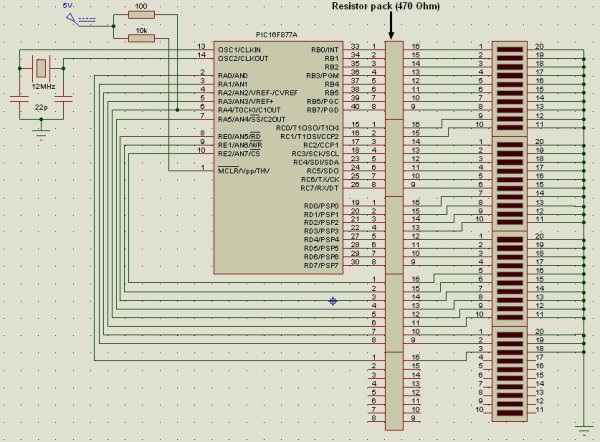
The Microchip PIC16F877A has 40 pins 33 of them can be input or output. In this simple project I am going to configure this microcontroller to blink a 33 LED each LED is connected to one I/O pin.
The PIC16F877A has 8 analog channels, so we have to configure all these channels as digital output.
The pin RA4 is an open drain output we must add a pull up resistor to turn it on and off.
The circuit schematic is shown by the following picture:
The code is written using MikroC PRO for PIC compiler:
void main(){ ADCON1 = 0x07; // Configure all analoge pins as digital PORTA = 0; TRISA = 0; // Configure PORTA as output PORTB = 0; TRISB = 0; // Configure PORTB as output PORTC = 0; TRISC = 0; // Configure PORTC as output PORTD = 0; TRISD = 0; // Configure PORTD as output PORTE = 0; TRISE = 0; // Configure PORTE as output while (1) { PORTA = ~ PORTA; // Invert PORTA status PORTB = ~ PORTB; // Invert PORTB status PORTC = ~ PORTC; // Invert PORTC status PORTD = ~ PORTD; // Invert PORTD status PORTE = ~ PORTE; // Invert PORTE status delay_ms(500); } } For more detail: PIC16F877A LED blink
About The Author
Ibrar Ayyub
I am an experienced technical writer holding a Master's degree in computer science from BZU Multan, Pakistan University. With a background spanning various industries, particularly in home automation and engineering, I have honed my skills in crafting clear and concise content. Proficient in leveraging infographics and diagrams, I strive to simplify complex concepts for readers. My strength lies in thorough research and presenting information in a structured and logical format.
Follow Us:LinkedinTwitter