Summary of PIC16F877 stop watch code and Proteus simulation
This article explains implementing a countdown stop watch on a PIC16F877 using Timer0-generated 1 ms interrupts, an LCD display, three RE0–RE2 pushbuttons for time setting, and an LED that lights when time reaches zero. The code is in C (MPLAB with HI-TECH C) and can be simulated in Proteus; downloads are provided.
Parts used in the PIC16F877 Stop Watch:
- PIC16F877 microcontroller
- 16x2 LCD module
- Timer0 (internal peripheral)
- Three push buttons (connected to RE0, RE1, RE2)
- LED D1
- Resistors for LCD, LED and buttons (pull-ups/pull-downs as required)
- Crystal oscillator or clock source for PIC
- Proteus simulation software (for verification)
- MPLAB IDE with HI-TECH C compiler
This PIC16F877 microcontroller tutorial answers the question,
” How to implement a stop watch using PIC16F877 ? ”
Using PIC16 simulator (Proteus) you can verify this stop watch code and change it according to your needs. Using three push buttons (As shown in figure below) you can adjust time as you desire. Then after setting the time, value displayed on the LCD starts to decrease with each second and when this value reaches zero, then LED D1 is turned on. This code is written in C language using MPLAB with HI-TECH C compiler. You can download this code from the ‘Downloads‘ section at the bottom of this page.
In this article, it is assumed that you know,
- How to make a simple digital clock using PIC16F877. If you don’t then please read this page.
- How to interface LCD with PIC16F877 microcontroller. If you don’t then please read this page.
- How to configure timer0 of PIC16F877 microcontroller. If you don’t then please read this page.
The following diagram (made in Proteus) shows the PIC microcontroller circuit diagram.
The above figure was taken when time was 00:00:07, i-e only 7 seconds were remaining until LED D1 is turned on. Timer0 is used as the base for digital clock generation. Timer0 is used here to generate 1msec interrupts. After every 1msec a global variable named msCounter increments. When msCounter reaches a value of 1000 then another global variable named secCounter decrements and this process repeats itself. Similarly, when secCounter reaches 0, then minCounter decrements. And when minCounter reaches 0 then hrCounter decrements. This process continues until hrCounter reaches 0. LCD is updated with the new values of hrCounter, minCounter and secCounter after every second.
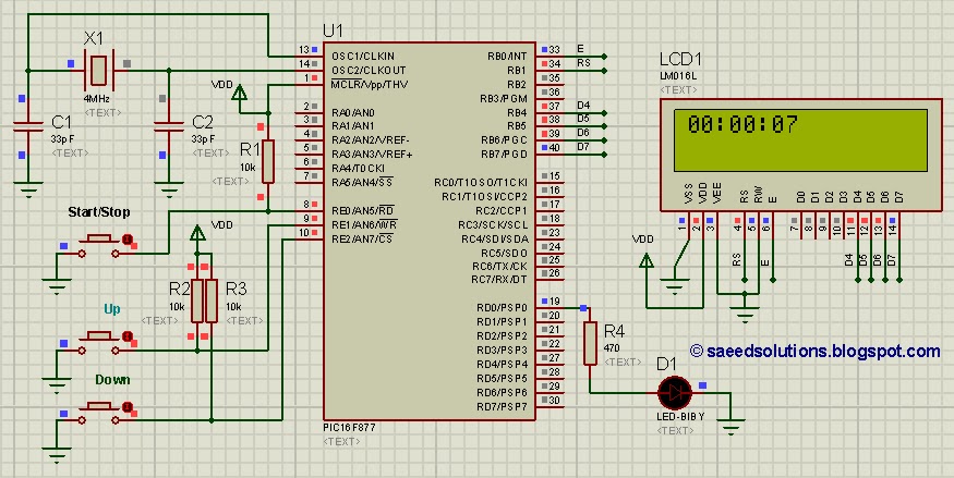
You can set time using three push buttons attached on RE0, RE1 and RE2 pins (As shown in the above figure). By pressing ‘Set Time‘ button one time, code enters in configuration state. Hours value starts to blink and you can modify it using Up and Down buttons. Pressing Up button increments the value and pressing Down button decrements the value. When you are done setting Hours value, press ‘Set Time‘ button again, then Minutes value will start to blink and you can adjust this value using Up and Down buttons. Similarly, after setting Minutes value, you can press ‘Set Time‘ button again, then Seconds value will start to blink and you can adjust this value using Up and Down buttons. When you are done adjusting the time, then press ‘Set Time‘ button for the last time and this stop watch will start to work normally.
Code
The main function code is shown below.
Downloads
Stop watch clock display code using PIC16F877 was compiled in MPLAB v8.85 with HI-TECH C v9.83 compiler and simulation was made in Proteus v7.10. To download code and Proteus simulation click here.
For more detail: PIC16F877 stop watch code and Proteus simulation
- How is timekeeping implemented in the stop watch?
Timer0 generates 1 ms interrupts; msCounter increments every 1 ms and when it reaches 1000 secCounter decrements, cascading to minutes and hours. - Can I set hours, minutes, and seconds on this stop watch?
Yes; pressing the Set Time button cycles through hours, minutes, and seconds which blink and are adjusted with Up and Down buttons. - What happens when the countdown reaches zero?
When hrCounter reaches 0 (time reaches zero), LED D1 is turned on. - Which pins are used for the time-setting buttons?
The three push buttons are attached to RE0, RE1 and RE2 pins. - How is the LCD updated?
The LCD is updated with hrCounter, minCounter, and secCounter values after every second. - What development tools and simulation software were used?
Code was compiled in MPLAB v8.85 with HI-TECH C v9.83 and simulated in Proteus v7.10. - Does the article provide downloadable code and simulation files?
Yes; download links for the code and Proteus simulation are provided in the Downloads section. - How do Up and Down buttons function during configuration?
Pressing Up increments the current blinking value (hours/minutes/seconds) and Down decrements it.