
Summary of PIC16F877 LCD code and Proteus simulation
This tutorial explains interfacing a 16x2 HD44780-based LCD with a PIC16F877 using HI-TECH C and MPLAB, and simulating the project in Proteus. It covers pin mapping, initialization, writing strings, DDRAM behavior, defining and displaying 8 custom characters, and using functions to scroll the display or cursor. Configuration options (4-bit mode, entry mode, LCD size, fonts) and editable pin macros are highlighted. Example shows saeedsolutions.blogspot.com displayed and the screen scrolling left with custom up/down arrows.
Parts used in the PIC16F877 LCD Project:
- PIC16F877 microcontroller
- 16x2 LCD with HD44780U controller
- Proteus simulator (for verification)
- MPLAB IDE
- HI-TECH C compiler
- Wiring between PIC ports RB0-RB7 and LCD (RS,RW,EN,Data bus)
- Power supply for PIC and LCD
- Optional resistors/potentiometer for LCD contrast (implied)
This PIC16F877 microcontroller tutorial provides very detailed and comprehensive LCD[1] code.
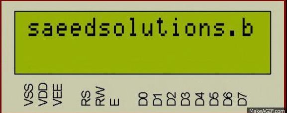
Using PIC16 simulator (Proteus) you can verify this LCD code and change it according to your needs. This code is written in C language using MPLAB with HI-TECH C compiler. You can download this code from the ‘Downloads‘ section at the bottom of this page.
It is assumed that you know how to blink an LED with PIC16F877 microcontroller. If you don’t then please read this page first, before proceeding with this article.
The following diagram (made in Proteus) shows the PIC microcontroller circuit diagram.
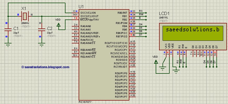
In the above figure, RB0 pin is being used as RS pin for LCD. RB1 pin is used as RW pin, RB2 pin is used as Enable pin and RB4 to RB7 pins are used as Data bus for the LCD. When code starts running then ‘saeedsolutions.blogspot.com‘ is displayed on the first line of LCD first. Also, on the second line in the end, two custom characters are also displayed (Downward arrow and Upward arrow). Then whole screen starts to scroll towards left. Following animation shows the result of simulating the code in Proteus.
Code
The code for the main function is shown below.
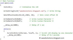
In the main function, firstly LCD is initialized using InitLCD() function. After that, ‘saeedsolutions.blogspot.com’ is written on the LCD screen[2]. In this way using WriteStringToLCD() function, you can write any string on the LCD screen. GotoYXPositionOnLCD(LCD_LINE2, 38) statement makes the DDRAM(Data Display RAM) pointer to go to LCD line 2 second last character position, this means that next character written to LCD will be displayed at this position. Each line of the LCD can have 40 characters saved in its DDRAM at most and only 16 characters are displayed at a given time[3].
There are 8 custom characters[4] defined in the code as well. At position 0x06 Downward Arrow custom character is defined and at position 0x07 Upward Arrow custom character is defined. These two characters are displayed at last position of LCD line 2 using WriteDataToLCD(0x06) for Downward Arrow and WriteDataToLCD(0x07) for Upward Arrow. Then there is delay of 1 second using __delay_ms(1000); statement.
In the while(1) loop, LCD screen is scrolled to the left by one character after every 0.2 seconds. This scrolling is achieved using the function ScrollLCD(ScrollScreen, ToLeft, 1), in which you can change ScrollScreen to ScrollCursor if you want to scroll cursor only. You can change ToLeft parameter to ToRight if you want to scroll towards right. You can change value 1 to any x number, if you want to scroll LCD by x characters instead of 1 character at a time.
In the code, custom characters[4] defined are shown below (From LCD.h file).
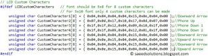
There are 8 custom characters defined. You can learn how to create these arrays from this link. Then you can replace these arrays with your own custom character arrays and those custom characters can be called from the main function if required.
In the code you can easily select the configuration for the LCD to be used. Following figure shows the pin selection code.
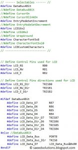
Here for example, you can change RB0 to RB3 if you want to attach RS pin of the LCD on pin36 of PIC16F877. You will also need to change LCD_RS_Dir to TRISB3 for RB3. Similarly, you can change other pin definitions as well.
In the Selectables, there are many macros defined. You should uncomment or comment these macros as per requirement. For example, the above code shows that LCD is being configured in DataBus4bit mode, Entry mode is set to increment with each character, 16×2 LCD is selected, character font is 5×8 and custom characters are being defined.
There are many functions available in LCD.c file which you can use in your code. This tutorial only covers few of these functions. You can leave your comments in the comment section below.
Notes and References
[1] Here LCD means most widely used common 16×2 LCD, which has HD44780U controller in it.
[2] As shown in Figure 1, “saeedsolutions.blogspot.com” is displayed in the Proteus simulation.
[3] This statement is valid only for 16×2 LCD. For 20×2 LCD 20 characters are displayed on LCD screen at a given time, but only 40 characters can be saved for each LCD line in DDRAM.
[4] Custom character are special characters, which you can store in the CGRAM(Character generator RAM) of LCD. These characters can be designed to display custom made character. For details on how to make these custom characters, you can check this link.
Downloads
LCD interfacing code using PIC16F877 was compiled in MPLAB v8.85 with HI-TECH C v9.83 compiler and simulation was made in Proteus v7.10. To download code and Proteus simulation click here.
For more detail: PIC16F877 LCD code and Proteus simulation
- How is the LCD connected to PIC16F877 in the example?
RB0 is RS, RB1 is RW, RB2 is Enable, and RB4 to RB7 are used as the 4-bit data bus. - Can I display long strings on the 16x2 LCD?
Yes; each LCD line can store up to 40 characters in DDRAM, though only 16 are visible at a time on a 16x2 LCD. - How are custom characters added to the LCD?
Eight custom character arrays are defined in LCD.h and stored in CGRAM; they are displayed using WriteDataToLCD with their positions (for example 0x06 and 0x07). - Does the code support scrolling the display?
Yes; the code uses ScrollLCD(ScrollScreen, ToLeft, 1) to scroll the screen left by one character every 0.2 seconds. - What tools are required to compile and simulate the code?
The code was compiled with MPLAB v8.85 using HI-TECH C v9.83 and simulated in Proteus v7.10. - How can I change which PIC pins connect to the LCD?
You can change the RBx pin definitions and corresponding TRIS macros in the pin selection code to map RS, RW, EN, and data lines to other pins. - Can the scrolling direction and amount be changed?
Yes; change ToLeft to ToRight to reverse direction and change the numeric parameter (for example 1) to scroll by more characters. - What LCD modes and options can be selected in the code?
The code allows selecting 4-bit data bus, entry mode increment, 16x2 LCD, 5x8 font, and enabling custom characters via macros.
