
Summary of PIC16CXXX real time clock electronic project
A simple real-time clock using a PIC16CXXX microcontroller employs Timer1 with its own crystal to keep time while the MCU sleeps. On startup the display shows 12:00 PM; Timer1 generates one-second interrupts to wake the device, update HRS/MIN/SECS, toggle the colon every other second, then return to sleep. Three buttons (select units, increment, clear minutes) set the clock. The design uses a Hitachi LCD in 4-bit mode, RC oscillator for the MCU core, and a 32.786 kHz crystal on Timer1 for accurate timekeeping.
Parts used in the Real Time Clock project:
- PIC16CXXX microcontroller (mid-range PIC16CXXX family)
- Timer1 32.786 kHz watch crystal
- RC network for OSC1 (approximate 4 MHz device frequency)
- Hitachi standard LCD display module (4-bit mode)
- SELECT_UNITS Key (S1)
- INC Key (S2)
- CLR_MIN Key (S3)
- Resistors and capacitors for RC network and general circuitry
- Connections/wiring to RA2:RA0 control pins and RB3:RB0 data pins
- Switch inputs connected to RB7:RB5
A very simple real time clock electronic project can be designed using the PIC16CXXX microcontroller family , designed by Microchip Technology . This real time clock electronic project uses the Timer1 module, from a mid-range PIC16CXXX microcontroller, to control a low-power real-time clock. Timer1 was chosen because it has its own crystal which allows the module to operate during sleep.
 Upon power-up, the device is initialized with the display starting at 12:00 PM, and Timer1 is configured to generate an interrupt (every second). The Timer1 overflow interrupt wakes the device from sleep. This causes the time registers (HRS, MIN, SECS) to be updated. If the SECS register contains an even value (SECS<0> = 0), the colon (“:”) is not displayed. This gives a visual indication for each second. Then the device returns to sleep.
For setting the clock are used three keys : SELECT_UNITS Key (S1) selects which units are to be
modified (hours, minutes, off), the INC Key (S2) increments the selected units and CLR_MIN Key (S3) clears the minutes and seconds (useful for exactly setting the time ) .
This simplify design use a standard Hitachi LCD display module and some other electronic parts .
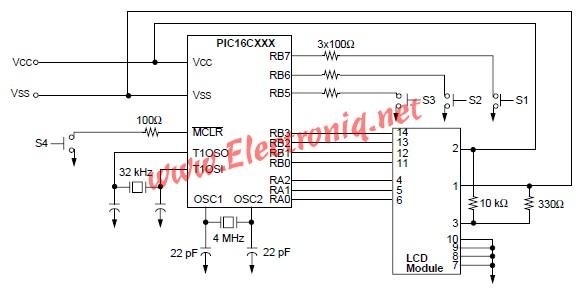 The RA2:RA0 pins are the control signals to the LCD display, RB3:RB0 acts as a 4-bit data bus, and RB7:RB5 are the input switches. The OSC1 pin is connected to an RC network, which generates an approximate 4 MHz device frequency. Because Timer1 operates asynchronously to the device, the device’s oscillator can be configured for RC mode.
Timer1’s crystal is connected to the T1OSI and T1OSO pins. A good choice for a crystal is a 32.786 kHz (watch) crystal.
This electronic project and source code was designed by Mark Palmer Microchip Technology Inc.
For more detail: PIC16CXXX real time clock electronic project
- How does the clock keep time while the microcontroller sleeps?
Timer1 has its own crystal and operates asynchronously, allowing it to run and generate interrupts while the device is in sleep. - What crystal is recommended for Timer1?
A 32.786 kHz watch crystal is recommended for accurate timekeeping. - How often does Timer1 generate an interrupt?
Timer1 is configured to generate an interrupt every second. - How is the colon on the display toggled each second?
If the SECS register contains an even value (SECS0 = 0), the colon is not displayed, creating a visible toggle each second. - Which pins control the LCD display?
RA2:RA0 are used as the control signals and RB3:RB0 act as the 4-bit data bus to the LCD. - Which pins are used for input switches?
RB7:RB5 are used for the input switches. - What buttons are used to set the clock?
Three keys: SELECT_UNITS (S1) to choose hours/minutes/off, INC (S2) to increment the selected unit, and CLR_MIN (S3) to clear minutes and seconds. - What oscillator mode is used for the device core?
The device oscillator can be configured for RC mode because Timer1 runs asynchronously. - What happens on power-up?
Upon power-up the device is initialized with the display starting at 12:00 PM and Timer1 configured to interrupt every second.
