Summary of PIC12F675 PC PROGRAMMABLE SECURITY SYSTEM
This article describes a cost-effective security system using the PIC12F675 microcontroller, designed for simple installation with a hidden switch instead of a keyboard. Key features include battery monitoring and adjustable parameters like delays and chirps, which can be configured via a Visual Basic program over a serial port. The PCB includes an optional header for in-circuit programming without removing the chip.
Parts used in the PIC12F675 PC Programmable Security System:
- PIC12F675 Microcontroller
- Hidden Switch
- Battery Monitor
- Visual Basic Program
- PC Serial Port (COM Port)
- Optional Programming Header
- Relay
- Siren
- TB1 Terminal Block
This project uses the 12F675, it was chosen because of its low cost, A/D convertor and flash memory. This security system was designed to be used in a simple installation with just a hidden switch and not a keyboard…. Electronics Projects, PIC12F675 PC Programmable Security System “microchip projects, microcontroller projects, picbasic pro examples,
This project uses the 12F675, it was chosen because of its low cost, A/D convertor and flash memory. This security system was designed to be used in a simple installation with just a hidden switch and not a keyboard. There are several features such as a battery monitor built into the code that also make it good for remote locations just run off a battery. Also all the delays and and other parameters are put into flash memory just by using a visual basic program and the serial port of a PC.
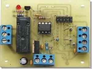
As you can see in the photo there are unused holes in the board, the board was designed for several different variations and future applications. Also the picture shows a optional header. This header connects to a switch on my programmer so that I flip the switch to “load” press the program button then switch to “run”. If I need to change the program all I need to do is flip the switch to “load” press the program button then switch to “run”, no need to unplug the IC or anything.If the header is to be used the 4 thin traces between the header need to be cut. The ground trace remains intact.
As mentioned above the delays and parameters can be programmed in anytime by the use of a visual basic program and the serial port on a PC. All you need to do is:
– start the VB program.
– connect the PC’s com port TX out pin to the Serial In on TB1 and PC’s com port ground pin to the ground on TB1
– select the correct Com port on the VB program and press Set Defaults.
– change any parameters
– connect 9 to 12 volts to TB1
– within 10 seconds of above press “Upload to Pic” , the program puts the PIC in program mode for only 10 seconds at power up
What the above parameters are
Entrance delay – the time you have to disarm the system with the hidden switch after the door switch is opened.
Exit Delay – the time you have to arm the system with the hidden switch and close the door.
Siren Timeout – the length of time the relay is activated after a alarm.
# of chirps ARMED – you may adjust the number of chirps that you get after a exit delay to confirm the system is armed. Enter 0 is you want none.
# of chirps TRIPPED – if the system has been tripped and after the siren timeout when disarm the system you you may adjust the number of chirps that you get. Enter 0 is you want none.
# of chirps LOW BATT- you may adjust the number of chirps that you get when a low battery condition is detected. Enter 0 is you want none.
Chirp time off – you can set the on/off ratio of the chirp here.
Chirp time on – you can set the on/off ratio of the chirp here.
Low Bat Chirp Int – you can set the interval that the low battery chirp comes on.
Low Battery – the level in tenths of a volt that will indicate a low battery ie 110 is 11.0 volts
Spare – not used
Spare – not used
Source: users.picbasic.org PIC12F675 PC Programmable Security System source code schematic pcb alternative link
FILE DOWNLOAD LINK LIST (in TXT format): LINKS-266.zip
Source: PIC12F675 PC PROGRAMMABLE SECURITY SYSTEM
- Why was the PIC12F675 chosen for this project?
It was selected due to its low cost, built-in A/D converter, and flash memory. - Can this system be powered by a battery?
Yes, it includes a battery monitor making it suitable for remote locations running off a battery. - How are delays and parameters programmed into the device?
They are programmed using a Visual Basic program connected to the PC serial port. - What is the purpose of the optional header on the board?
The header connects to a programmer switch allowing users to load new programs without unplugging the IC. - What happens if the header is not used?
If the header is not used, the four thin traces between the header must be cut while the ground trace remains intact. - How do you upload changes to the PIC?
You connect power to TB1, wait within 10 seconds, then press Upload to Pic in the VB program. - What does the Entrance Delay parameter control?
It sets the time allowed to disarm the system with the hidden switch after a door switch opens. - How is the Low Battery level configured?
It is set in tenths of a volt, where entering 110 indicates a low battery at 11.0 volts. - Can you disable the confirmation chirps?
Yes, entering 0 for the number of chirps will result in no chirps being played.