
Summary of PIC Waveform Recorder
This article demonstrates a PIC microcontroller project that records and replays waveform patterns. The system samples input signals using the internal A/D converter, stores up to 256 8-bit data points in EEPROM, and reconstructs the analog signal via an external I2C D/A converter. While limited by I2C speed and memory size, the design effectively handles low-frequency signals for basic waveform generation and testing purposes.
Parts used in the PIC Waveform Recorder:
- PIC Microcontroller
- EEPROM Memory
- Signal/Waveform Generator
- PIC Internal A/D Converter
- External I2C 8-bit D/A PCF8591
- PIC Programmer
- RIGOL DG4062 Waveform Generator
- DS2072 Oscilloscope
In this article I’ll show you how you can use PIC microcontroller to record and store waveform patterns in its EEPROM memory and replay the sequence later. For this purpose we’ll need a signal/waveform generator to produce the signal, PIC internal A/D converter to sample and digitize the incoming signal, external I2C 8-bit D/A PCF8591 to convert it back to analog form and a simple PIC programmer to download the code into microcontroller FLASH memory. Up to 256 discreet 8 bit words then will be stored in PIC EEPROM memory. Source code can be downloaded at the bottom of the page.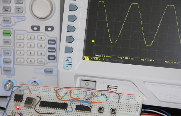
Few words about the code: The source code is written in assembly language and uses Microchip EEPROM writing/reading sequence as a basis for signal recording. For simplicity reason only 128 of 256 available bytes are used. To test circuit functionality connect the signal source to AN1 input and Scope to digital to analog converter output. I’ve used RIGOL DG4062 waveform generator and DS2072 oscilloscope to test this design. Press Record push button to record one cycle of the wave. Now you can disconnect the generator. Press Play to output one cycle of the recorded waveform. Signals in the lower KHz range seem to work OK. Next figure shows the schematic of this simple design.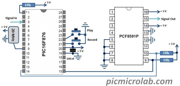
Limitations and possible future improvements of current design: A better synchronization routine is needed in order to avoid glitches while reproducing the recorded waveform. The beginning of the next cycle should start exactly were the previous cycle has stopped. The best way to improve the quality of the signal is to increase the memory size so you can store more waveform values in one cycle, also signal frequency range is limited due to I2C speed limit for A/D converter, currently set at 100KHz. Faster D/A should be used to increase the frequency range. Source code is here.
For more detail: PIC Waveform Recorder
- How many discreet 8 bit words can be stored?
Up to 256 discreet 8 bit words can be stored in PIC EEPROM memory. - What language is the source code written in?
The source code is written in assembly language. - Which input pin should be connected to the signal source?
Connect the signal source to the AN1 input. - Can the generator be disconnected after recording?
Yes, you can disconnect the generator after pressing Record to output one cycle of the recorded waveform later. - What frequency range works best with this design?
Signals in the lower KHz range seem to work OK. - Why is a better synchronization routine needed?
A better synchronization routine is needed to avoid glitches while reproducing the recorded waveform. - How can the quality of the signal be improved?
The best way to improve quality is to increase the memory size to store more waveform values in one cycle. - What limits the signal frequency range?
The signal frequency range is limited due to the I2C speed limit for the A/D converter.
