
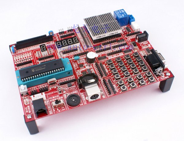
Summary of PIC microcontroller development board using pic microcontroller
This development board features a modular backplane design for versatile PIC microcontroller experiments. It includes comprehensive instructions and a simple programmer to facilitate rapid hardware and software testing. The system supports various components like LEDs, LCDs, sensors, and communication interfaces, allowing users to customize setups for learning and prototyping.
Parts used in the PIC Microcontroller Development Board:
- PIC16F887 microcontroller (standard) or other DIP40 package PICs
- 8 green patch light-emitting diodes
- 1 red LED digital tube
- 4-digit red LED display
- 4 x 8 x 8 LED dot matrix screen
- 1602 LCD module
- 12864 Graphic LCD module interface
- PCF8563 RTC with crystal and battery holder
- Potentiometer for A/D conversion experiments
- Onboard RS232 serial interface circuit
- DS18B20 temperature sensor
- PS/2 keyboard interface
- Relay with normally open contact
- 38KHz integrated infrared receiver
- IR remote control
- 8 independent keys with pull-up resistors
- 4 x 4 matrix keys with pull-up resistors
Development board backplane
Plug-in part by wave soldering process , the board also neat reverse .
The curved surface of the pad foot , guaranteed not to scratch your desktop.
The system uses a fully independent module design , DIY leave enough space to the user
can use any combination of the modules for a variety of experiments.
The benefits of individual modules is self-evident , but for beginners operation is relatively
cumbersome , we prepared a detailed operating instructions for each experiment , including plug wire method ,
with plug wire schematics.This allows to users in the shortest possible time , to develop, test and fix it’s software & hardware.
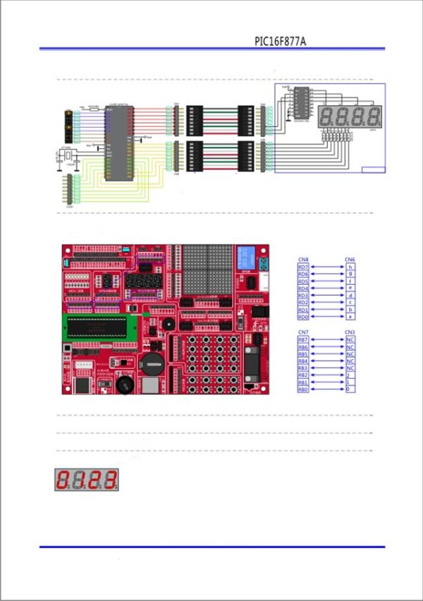
 Full instruction for every component (sample page)
Operation of the programmer is very simple, just press the icon PP2011
The programmer automatically will recognizew the board and install the communication
betwee it and the PC. You then can choose your .hex file , adjust ( if you want ) the flage
and programme the microcontroller.
Prammer Supported Devices :
PIC16F5X series : PIC16F54, PIC16F57, PIC16F59
PIC16F7X series : PIC16F72, PIC16F73, PIC16F74, PIC16F76, PIC16F77
PIC16F7X7 series : PIC16F737, PIC16F747, PIC16F767, PIC16F777
PIC16F87XA series : PIC16F873A, PIC16F874A, PIC16F876A, PIC16F877A
PIC16F88X series : PIC16F882, PIC16F883, PIC16F884, PIC16F886, PIC16F887
PIC16F91X series : PIC16F913, PIC16F914, PIC16F916, PIC16F917, PIC16F946
Board within the resource description SCM:
The standard configuration comes with a PIC16F887, the user can replace it with other DIP40 package PIC microcontroller, as :
PIC16F874A, PIC16F74, PIC16F77, PIC16F747, PIC16F777, PIC16F874, PIC16F877, PIC16F914, PIC16F917 ecc. ecc.
Light-emitting diodes: 8 green patch of light-emitting diodes, light water experiments can be done .
Digital tube: 1 red LED , digital tube early learning , this is the best , easiest to grasp the principle . 4 -digit red LED, learn static display ,
the use of this learning dynamic display four digits.
LED dot matrix : 4 x 8 × 8LED matrix , composed of 16 × 16 dot matrix screen.
1602 LCD Interface: 1602 LCD module interface. The board comes with an LCD1602 as free gift.
12864 Graphic LCD Interface: 12864 LCD module interface , the LCD module can be inserted. Text, images , animation experiment.
RTC (real time clock) : the PCF8563, crystal (32768Hz), back-up battery holder components. ( coin batery is not included)
A/D ( analog – digital conversion ) : By a potentiometer, by switching the jumper , you can experiment with any of the analog ports of the microcontroller.
RS232 serial interface : Onboard RS232 Interface circuit , you can easily use it to communicate with PC or other devices.
 Temperature sensor: switching jumper from the DS18B20 and composed by DuPont wire can make it take on any IO port .
You can control and display ( on any display you wish) the temperature of the experiment .
PS/2 keyboard interface : You can conect any PS/2 keyboard interface , the keyboard decoding experiments .
Relays and contacts: The relay has a relay normally open contact.
IR receiver : Onboard 38KHz Integrated infrared receiver,. The set comes withan infrared remote control.
Signals can be decoded.
8 independent keys : 8 indipendent keys , each key has a pull-up resistor.
4 × 4 matrix keys : 16 keys consisting of 4 × 4 matrix , with a pull-up resistor.
For more detail: PIC microcontroller development board
- How do I program the microcontroller?
Press the icon PP2011 to automatically recognize the board, install communication with the PC, select your .hex file, adjust flags if needed, and program the device. - Which PIC microcontrollers are supported by the programmer?
The programmer supports devices from the PIC16F5X, PIC16F7X, PIC16F7X7, PIC16F87XA, PIC16F88X, and PIC16F91X series. - Can I replace the standard microcontroller on the board?
Yes, the user can replace the standard PIC16F887 with other DIP40 package PIC microcontrollers such as the PIC16F874A or PIC16F917. - What is included with the board regarding displays?
The board comes with an LCD1602 as a free gift and includes interfaces for a 12864 graphic LCD, along with built-in LEDs and digital tubes. - How can I perform analog-to-digital conversion experiments?
You can use a potentiometer and switch the jumper to experiment with any of the analog ports of the microcontroller. - Does the board support real-time clock functionality?
Yes, it includes a PCF8563 RTC with a 32768Hz crystal and a backup battery holder, though the coin battery is not included. - How do I connect the temperature sensor?
You can switch the jumper to connect the DS18B20 sensor via DuPont wire to any IO port for temperature monitoring. - Is an IR remote control provided with the kit?
Yes, the set comes with an infrared remote control that works with the onboard 38KHz integrated infrared receiver.
