


Summary of PIC Based Speed Controller using PIC16C54
This article describes an inexpensive DC motor speed controller using a PIC microcontroller. It utilizes Pulse Width Modulation (PWM) for efficiency and adapts the Radio Control (R/C) servo pulse standard to control motor direction and speed. The hardware employs an opto-isolator for noise protection and power transistors to drive the motor, allowing operation from separate voltage supplies.Parts used in the PIC Based Speed Controller:
- PIC16C54 microcontroller
- Opto-isolator chip
- TIP 125 PNP power darlington transistors
- TIP 120 NPN power darlington transistors
- 470 ohm resistor pack
- Resistors R1 through R4
Introduction
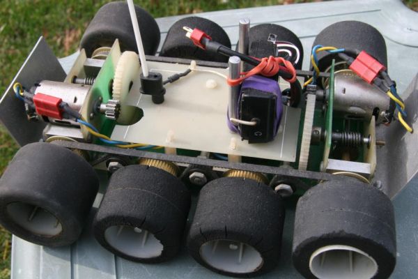
Real world applications often call for controlling small to medium sized DC motors from digital circuits. For smaller motors it is usually economically infeasible to buy a commercial speed controller as the cost of the controller will far outstrip the cost of the motor itself. The PIC's high speed, low cost, and low power requirements lend it to being an inexpensive "smart chip" controller for DC motors.
Background
Many modern speed controllers for DC motors use a technique called Pulse Width Modulation (PWM) to control the speed of the motor. Using a switching device such as a power transistor or enhancement mode MOSFET, power is switched on an off rapidly to the motor. The natural inductance and resistance of the motor acts as a low pass filter and makes the effective voltage seen by the motor to be the average value of the voltage over time. By varying the duty cycle (width) of this switched voltage, the effective average voltage can be lowered (narrow width pulse) or raised (wide pulse). This produces the effect of a linear change in voltage, however since the switching device is either off or in saturation it is never required to dissipate too much power internally. This increases the overall efficiency of the system as well.
The other half of the problem is how to tell the motor controller what speed you would like the motor to be set to. Any of a number of schemes would work, however the Radio Control (R/C) community has a standard for controlling servos that is particularly apt for this application. This standard uses a pulse, of variable width, repeated periodically to specify the "position" of the servo. The position variable in the servo can take on values from "full retract" to "full extension" and any position in between. Where the servo is positioned is determined by the width of this incoming pulse. In this application we will use this same technique, however rather than full retract or full extension our controller sets the speed of the motor it is controlling from full reverse to full forward.
The control pulse is defined by the width that represents "neutral," or in the case of the motor controller the width that represents "stop," and the change in width or delta that will yield full travel. A typical value for neutral on a Futaba R/C servo is 1520 uS, however for me it was easier to use 1500 uS. Depending on the servo, the "maximum" and "minimum" position will be some delta plus or minus this neutral position. On a Futaba S143 servo that I tested, these values were 700 uS for the minimum or full retract position and 2300 uS for maximum or full extension position. Generally they land near the 1000 uS for a minimum pulse width and 2000uS as a maximum pulse width. Given the timing constants of the program, this program responds to pulses that are between 860 uS and 2140 uS. The exact relationship is shown in Figure 1.
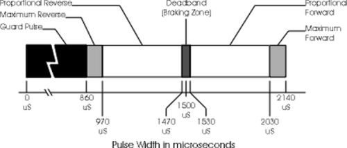
The last piece of this specifcation is how often one needs to send the control pulse to the servo. Again using the Futaba servo as a reference it is about every 20 mS or 50 times a second. Thus, the motor controller keeps the motors "on" at the current setting until either a new pulse arrives with the same or different width, or until approximately 20 mS has passed without seeing a new pulse.
How It Works
The hardware for this project is straight forward. Referring to the schematic shown in Figure 2. "The Motor Controller Schematic" you will see that the input from the controller is fed into bit RB0. Port A of the PIC is connected to an opto-isolator chip. The purpose of this chip is to shield the digital side of the circuit from the electronic noise generated by the motors being switched. Further, it allows the motors to be easily run from a separate, and potentially much higher supply voltage. Resistors RP1a through RP1d are four elements of a 470 ohm resistor pack. There use is to imit the current in the opto-isolator LEDs to less than 10mA. The other side of the opto-isolator is used to drive the power transistors. Q1 and Q2 in the schematic are TIP 125 PNP power darlingtons and Q3 and Q4 are TIP 120 NPN power darlingtons. Resistors R1 through R4 are chosen to create a current of greater than 6mA through the bases of the transistors. The current can be greater, but should never be less than 6 mA.
For more detail: PIC Based Speed Controller using PIC16C54
Quick Solutions to Questions related to PIC Based Speed Controller:
- Why is a commercial speed controller often avoided?
It is economically infeasible because the cost of the controller far exceeds the cost of the motor itself. - How does PWM increase system efficiency?
The switching device is either off or in saturation, meaning it never dissipates too much power internally. - What standard is used to determine motor speed?
The project uses the Radio Control (R/C) community standard for controlling servos. - What pulse width represents the neutral stop position?
A typical value for neutral is 1520 uS, though 1500 uS was used in this specific application. - What is the purpose of the opto-isolator chip?
It shields the digital side of the circuit from electronic noise generated by the motors. - Can the motors run on a different supply voltage?
Yes, the opto-isolator allows motors to be easily run from a separate and potentially higher supply voltage. - What are the minimum and maximum pulse widths supported?
The program responds to pulses between 860 uS and 2140 uS. - How often must the control pulse be sent?
The pulse should be sent approximately every 20 mS or 50 times a second.
Related projects
CAN FD Node based on a PIC18 Microcontroller
The introduction sets the stage for an embedded systems project that involves developing a Embedded C CAN FD project using the MCP2517FD...
Communication & InterfacingLAN9662 Gigabit Switch: Optimized for Industrial Ethernet
Introduction It should come as little surprise therefore that one element of what is now more commonly referred to in some circles...
Communication & InterfacingPIC Microcontroller: Fundamentals & Applications for Students
Introduction Microcontrollers are the key components in the embedded systems market. A variety of embedded systems was formed and developed after the...
Communication & Interfacing10BASE-T1S Ethernet: Simplified OEM Design for Auto Devices
Introduction Cars these days are surrounded by technology. They come loaded with all sorts of electronic gadgets and sensors. This project wants...
Communication & InterfacingDesigning a Microcontroller Framework for PC-Based Control of Electrical Appliances
ABSTRACT The preference for personal computers as a platform for designing and implementing control algorithms is growing due to the ease of...
Communication & InterfacingEfficient Multichannel Data Acquisition with USB Connectivity using PIC Microcontroller
1. INTRODUCTION With the rapid advancements in embedded technology, there is a growing demand for a data acquisition system that combines fast...

Ibrar Ayyub
I am an experienced technical writer holding a Master's degree in computer science from BZU Multan, Pakistan University. With a background spanning various industries, particularly in home automation and engineering, I have honed my skills in crafting clear and concise content. Proficient in leveraging infographics and diagrams, I strive to simplify complex concepts for readers. My strength lies in thorough...