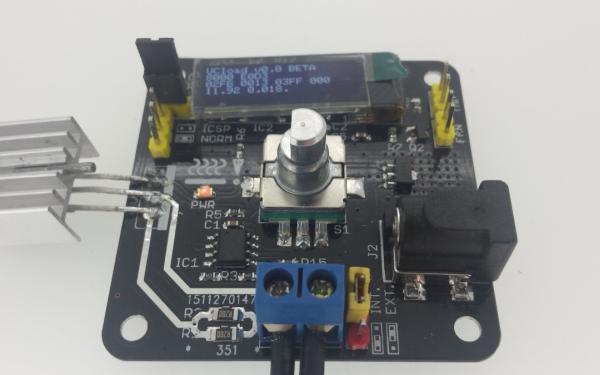
With no snow outside I finally got around to solder the 3rd PCB. It is the second revision of a microcontroller dummy load. It is loosely based on the arachnidlabs uc:load. It uses the same base ciruit and adds a microcontroller (PIC16F1825), rotary encode switch, external powersupply and offcourse a 128×32 OLED.
The picture shows a quick and dirty firmware I wrote. The top line states it is as BETA as it get, so no warranties there :). The second line displays the rotary counter and the 1ms ticks, the next the raw ADC values (Vin, Iin and Tamb) and the Iset setting. The last line displays the calculated Vin and Vout. The dot stated the rotary encoder isn’t pressed (a ! is displayed when pressed).
The FET is controlled through an opamp which compares the DAC from the microcontroller with the voltage across a 0.1 Ω shunt. The range is upto 1A (actually 1.024A), which is the range I was looking for. Using different resistors in the opamp stage could give other ranges. The FET is capable of voltages upto 30V, however the voltage divider used would limit it to 16V. My intendent use of this dummy load is to do basic measurement on some batteries I have lying around, and testing of the power supply I’m still designing (if ever finished).
The prototype does work but the firmware is far from finished, as far as I can see the hardware seems to be ok. A quick test with a DVM shows the current reading and voltage readings are within specs. I noticed some small silkscreen defects but does it require a new revision? Time will tell…
For more detail: PCB 3: UCload
