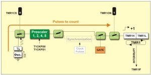
How to generate specific delay’s using Timers: The internal structure of Pic Microcontroller’s
This 5Mhz frequency can further be divided to operate a particular peripheral on different or desired frequency, by activating internal prescaler’s.

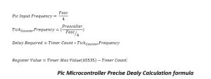
Pic Microcontroller Delay Calculation formula
Pic Microcontroller Delay Calculation formula
Tick/Counter frequency is the final frequency on which the timer is working.
Timer Count
Timer Count is the number of counts required to generate a particular delay/frequency at output of microcontroller pin. Timer count is the final value to be loaded in TMRxH and TMRxL Registers.
Register Value
Register Value must not be negative or grater than 65535. Since timer is a 16-bit and max 16-bit value is 65535
Lets calculate 1 second delay
Note: I am calculating value for 10 ms and then running the 10 ms delay 100 times to produce 1 second delay.
Pic input frequency= Fosc / 4= 20 Mhz / 4 = 5 Mhz
Prescaler = 1:4
Tick Counter frequency = Prescaler/5 Mhz = 4 / 5 Mhz = 0.8 u s
Delay required = 10 ms
Delay required = Timer Count * Tick Counter frequency
Timer Count = Delay required / Tick Counter frequency = 10 m s/ 0.8 u s = 12.5 k = 12500 (Hexadecimal = 0x30D4)
Register value = 65535 – 12500 = 53035 Value not negative and under 65535, its safe we can use 12500.
Timer counter value for 10 ms delay comes out to be 12500 which is in 16-bit range and we can load it in our timer registers. If i directly calculate 1 second value for timer count it comes out to be greater than 65535 hence 1 second delay can not be directly generated with the above given information. We have to adjust prescaler or input frequency for directly generating 1 second delay. For this tutorial i am only going with the 10 ms and running it for 100 times for 1 second delay.
Below is a test program in which i uploaded the above settings. Pic16f877a microcontroller is used in the project. Xc8 compiler and MPLABx is used for code compilation. An external 20 Mhz crystal is used as clock source. An led is connected at output of port-b pin#4. Timer-1 of pic16f877a is used to generate 1 second delay. Led toggles after every 1 second.
| /************************************************** | |
| * Property of: www.microcontroller-project.com * | |
| * Author: Usman Ali Butt * | |
| * Created on 8 April, 2017, 2:30 PM * | |
| **************************************************/ | |
| #include <stdio.h> | |
| #include <stdlib.h> | |
| #include <pic16f877a.h> | |
| void Timer0Delay(void); //Delay Function | |
| #define Dpin PORTBbits.RB4 //Delay output Pin Port-B pin#4 | |
| int main(int argc, char** argv) { | |
| TRISBbits.TRISB4=0; //Port-B pin 4 as output | |
| while(1){ | |
| Dpin^=1; //Toggle Output | |
| Timer0Delay(); //Delay | |
| } | |
| return (EXIT_SUCCESS); | |
| } | |
| void Timer0Delay(void){ //10ms delay | |
| T1CON=0x01; //Timer-1 16-bit mode Prescaler 1:4 | |
| TMR1H=0x30; //Count Hight Byte | |
| TMR1L=0xD4; //Count Low Byte | |
| //Runing loop for 100 times produces 1 second 10ms x 100 = 1 second | |
| for(int i=1;i< =100;i++){ | |
| T1CONbits.TMR1ON=1; //Run timer | |
| while(INTCONbits.TMR0IF==0); //Wait for flag to over flow | |
| T1CONbits.TMR1ON=0; //Switch off timer | |
| INTCONbits.TMR0IF=0; //Clear Interrupt | |
| } | |
| } |

