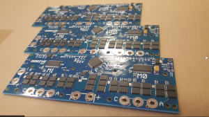
Description
However, brushless motors are not unique to expensive industrial automation equipment. In fact, you can get some very powerful and cheap motors at hobby shops. The electronics to drive these motors are also dirt cheap. So how come virtually no non-industrial automation systems use them?
To be honest, I have no idea. Seriously, a driver that allows this should clearly exist.
But since it didn’t, I decided to make one.
And you are invited!
This project is open source, both in hardware and software, and I warmly welcome anyone who wants to join
Details
Key specs:
- 2 motor channels
- 1 DC-DC converter channel: For powering the system with an arbitrary voltage power supply.
- 24V bus voltage
- 150A peak motor current
- 75A peak DC-DC current
- Encoder feedback for arbitrarily precise movements
- Supports power regeneration
- Use of a high power density Li-Po battery means you can achieve >1kW peak power output with only a modest power supply.
- It will feature various optimal control strategies and motion profiles.
- Permissive licence on both hardware and software: You use this project in anything you like, even commercial products (as long as you attribute this project’s contributors).
- Low cost: The target is to reach less than $50 for a fully assembled board.
Demos
The design is based on two earlier prototypes.
Here are some very simple demos with v2. The peak power output in these tests were only about 60W. The new version (v3) will be able to deliver much more power.
The drive is designed to be able to deliver incredibly high peak power, more than 1kW per motor channel. However, power supplies that can deliver this kind of power are expensive. Also, when the actuator is being decelerated, there is energy absorbed. Most power supplies do not like having energy dumped back into them.
The solution: Put high-power energy-storage on the DC bus. A battery like this one can deliver around 3kW. These types of batteries also have a fairly high charge rating, and if the regeneration is only over a couple of 100 milliseconds, they can probably handle a fair bit more than specified. Thus, they should be able to handle the full range of regeneration power in most robotics applications.
This means we have a variable voltage DC bus, that fluctuates with the battery’s state of charge. So the way we power the system is via a DC-DC converter. There is another upside to this as well: we can use any voltage power supply and just convert it to the bus voltage. I expect most people will use an inexpensive ATX power supply (specifically the 12V rails). In many robotics applications the motion consists of several discrete movements, only some of which are high power. In this case, we can have access to a very high peak power, but only require a very modest power supply.
Another thing that’s nice about using a battery for stabilising the DC bus, is that if multiple of these drives reside on the same bus, there is no fighting over the regulation of the bus voltage: a single board can have the DC-DC connected to a PSU, and the rest of the boards in the system can just use the bus. If fact, you can even skip populating the DC-DC on the slave boards.
Applications
So this project is good for some things, but not everything.
You should use this drive in your project if:
- You need high power: >1kW peak power per channel!
- You need high precision: Encoder feedback control means that the precision is as high as your encoder’s precision, which can be very very high.
- You need reliability: Encoder feedback ensures that the drive recovers from positioning errors: no more missed steps.
You should not use this drive in your project if:
- You need high torque, but don’t care about speed, and you don’t want to use any gearing. If this is the case, steppers are probably better for your project
- If you are interested in very tiny motors and robots, then you should check out these awesome micro robots instead!
For more detail: ODrive – High performance motor control


