Summary of Nokia 3315 / 3310 LCD interfacing with Microcontroller
Summary (under 100 words): This project demonstrates using a cheap, low-voltage Nokia 3310/3315 PCD8544 graphical LCD (84x48 pixels) with a 3V microcontroller to display large-font text and graphics. The demo uses a Microchip PIC18F458 and C with MPLAB. The article explains the LCD memory addressing (banks and X/Y axes), vertical addressing byte transfer sequence, and the required serial initialization sequence of command bytes to configure extended instruction set, operating voltage, temperature coefficient, bias system, and basic instruction mode.
Parts used in the Nokia 3310/3315 Graphical LCD project:
- Nokia 3310 or 3315 monochrome graphical LCD (PCD8544)
- Microchip PIC18F458 microcontroller
- 3V power supply (battery)
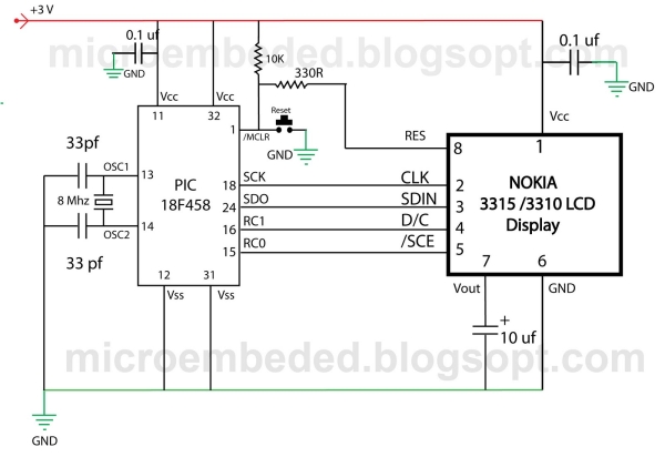
- Serial data connection lines: SCE, D/C, SDIN, CLK
- Wiring/connector to 8-pin LCD connector
- MPLAB IDE and C compiler/toolchain
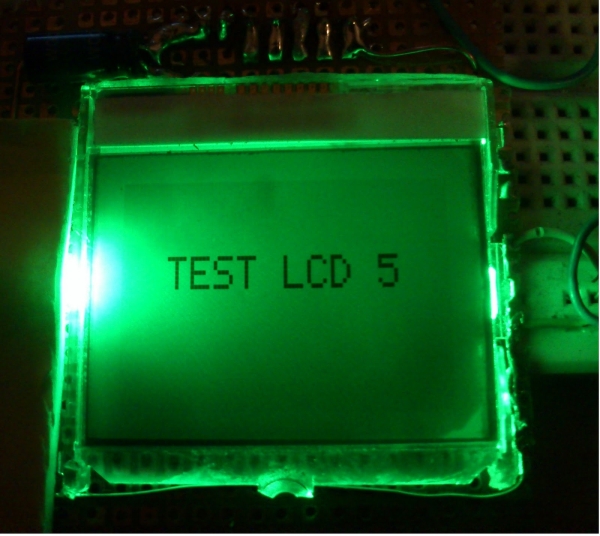
Displaying content on a normal alphanumeric display is very limited ,we have to be limited with the font size and we can’t draw any graphics also. but convention Graphics lcd are really very expensive so here is the solution, you can use Nokia 3315 / 3310 monochrome LCD to display your large font text and graphics . the reason behind using this LCD is ,it is really very cheap and can be powered with 3 volts supply. so it is really good for battery powered application.
Project Description
however you can use almost any microcontroller (with capability to work on 3v ) do display content on this LCD, may be that micro controller is PIC , AVR or MSP 430 , but in this demonstration we will be using Microchip PIC 18F458 Microcontroller.
 The software program for this project will be written in C with MPLAB IDE , This LCD has a resolution of 84×48 pixel.
About LCD:-
Nokia 3315 / 3310 Graphical LCD uses PCD8544 Controller chip From Philips. It is a chip-on glass(COG) with 8 pin connector on the back side of the LCD . You can refer to its datasheet for more information about this controller. (CLICK HERE TO DOWNLOAD PCD8544 Controller DATA SHEET).we will discuss only few main points here for out project purpose.
The typical example of RAM is shown in the figure blow, The vertical axes area addressed form 0 to 5 with eight bits for each address when combining with x axes, it can be represented as bank.
The horizontal axes are addressed form 0 to 83 and each bit will refer the corresponding pixel in X direction.
Addressing Mode
There are two type of addressing mode in this LCD
Vertical addressing Mode
A byte is sent to The LCD as follows:-
1:- Set SCE To GND
2.Set D/C to required state (Data or command)
3.Place a bit in SDIN line
4. Make high-to-low transition in CLK input.
5.Repeat step 3 and 4 for the remaining seven bits.
The initialization sequence of LCD
1. Pull SCE line to Ground to Enable The LCD.
2 Set D/C pin low to send commands to the LCD.
3. Write 0x21 Byte to LCD on the serial Bus. Here the LCD operates in Function set Command For extended instruction set.
4. Write 0xC8 Byte to LCD on the serial Bus. This set the operating voltage (Vop) of the LCD.
5. Write 0x06 Byte to LCD on the serial Bus. This set the temperature coeffcient.
6. Write 0x13 Byte To LCD on the serial Bus. This set the bias system of the LCD.
7. Write 0x20 Byte To LCD on the serial Bus. This allow the LCD to operate in function set command with basic instruction.
For more detail: Nokia 3315 3310 LCD interfacing with Microcontroller
- Can I use a Nokia 3310/3315 LCD for graphics and large fonts?
Yes. The Nokia 3310/3315 graphical LCD (PCD8544) supports graphics and large-font text on its 84x48 pixel matrix. - What microcontrollers can drive this LCD?
Almost any microcontroller capable of operating at 3V can be used, for example PIC, AVR, or MSP430; the demonstration uses PIC18F458. - What is the LCD resolution?
The LCD has a resolution of 84x48 pixels. - Which controller chip does the Nokia 3310/3315 LCD use?
It uses the PCD8544 controller chip from Philips. - How is a byte sent to the LCD in vertical addressing mode?
Pull SCE low, set D/C appropriately, place a bit on SDIN, toggle CLK high-to-low, and repeat for all eight bits. - What is the initialization sequence for this LCD?
Enable LCD by pulling SCE low, set D/C low, send 0x21, 0xC8, 0x06, 0x13, then 0x20 on the serial bus in that order. - What does sending 0x21 do during initialization?
It sets the LCD to Function set command for the extended instruction set. - Why is this LCD suitable for battery-powered applications?
Because it is inexpensive and operates at a low 3V supply, making it suitable for battery power.