Previously published as automatic charging system is the advanced version of my project I designed a new system using the 16F876. Without much change in the electronic portion of the system say the changes made in the program. I… Electronics Projects, Negative Delta-V Battery Charging Circuit LCD Display PIC16F876 “microchip projects, microcontroller projects, pic16f876 projects, picbasic pro examples,
Previously published as automatic charging system is the advanced version of my project I designed a new system using the 16F876. Without much change in the electronic portion of the system say the changes made in the program. I have done previous system 16C711 (once programmable) was working with the pic. Also cut off the end of the charging process is that the battery is full to understand that I was used Negative Delta-V system.
For those who are negative delta-V’s once again let me explain what I mean. quite voltage charging NiCd and NiMH batteries are rising. Following the rise of the voltage of the battery is cut off and stuffed after this stage of 10-20 mV per battery is a voltage drop. If you need to give examples of when one NiCd battery discharged voltage of around 0.8 V is about.
If you are charging this battery with a fully charged battery voltage 1.7 V to instantly remove. If we mV 1700 mV indicates this level. Due to the interest. Because from the moment of filling this voltage drops to 1680 mV. After this stage, if you continue to charge the battery starts to overheat. This is captured as a result of falling back measurement is judged battery full and charging is terminated.
My first interruption of the charging system is based only negative was to delta_v. However, some (generic) batteries that caught this fall or very difficult moment captured noticed that. So I’ve added to the system also kontrolünü voltage. As a result the negative delta-V y of the new program and by controlling the voltage of the battery charging process which terminates catches.
Another change was the previous circuit works relatively universal. So at least 2 units with a record total of 8 to connect the battery to the battery pack can be recharged without any settings, respectively. However, this leads to some problems when I noticed that the new program will be charged battery decided to enter the number. Therefore, in the new program registration still be at least 2 units can charge the battery with 8 total.
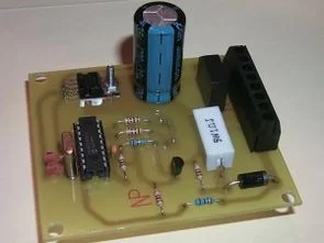
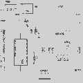
PIC16F876 BATTERY CHARGING CIRCUIT
The above circuit 2 to about 8 AA batteries can charge up the battery pack automatically. Upon the first start of the program the SET button is pressed. How many battery charge by pressing the Set button will be entered into the program and the charging process is started by pressing the SET key again.
Evil is on the order of 700 mA current. Account logic is as follows;
However, the LM317 can provide a maximum current of 1 amp (1000 mA) are to be considered in the calculation of these values must be used with or instead of 3 amps.
Fast charging system is working with logic. In this case, 1 amp (1000 mA) batteries for about 1.4 hours, and 2.8 hours in 2000 mA battery can charge like. Operating logic of the system is as follows.
1, first check whether the circuit is connected to a battery. 2 volt battery on the values indicates the presence. Mind control status of the battery is empty before charging current is given over a period of 1 sec. This position is both LEDs off.
If the circuit is connected to the battery 2 in the battery for 30 seconds to stabilize. is taken to stand for.
In this position, the red LED is ON, the green LED is OFF.
3 to about 4 minutes After this time 20% of the battery charge current is applied. In this position, the red LED is ON, the green LED flash is offline.
4 After this time the current is applied to the battery is fully charged. This position is both LED flash.
Following filling of the battery 5 to the battery 4% trichloroacetic called charge is applied to the charging stand. This ensures that the batteries remain connected as long as the discharge. In this position, the green LED is ON Red LED OFF.
Following the expiration of the battery charging voltage and current is automatically cut. Tepit of breakpoints in both negative Delta V charging system and eventually reach the required voltage of the battery is made by. In this system, after reaching a fully charged batteries continue charging the battery per case of 10 mV within a certain period starts falling. After allowing the battery to charge this fall should be discontinued. After this point to continue charging the battery case and will start to heat distortion will begin.
Circuit of the LM317 as current followers have been carried out by the method of attachment so that the charging voltage is adjusted automatically according to the number of batteries. Been tried with success is working with the entire circuit.
Charging circuit’s source PicBasic Pro and hex codes:
FILE DOWNLOAD LINK LIST (in TXT format): LINKS-12130.zip
Source: NEGATIVE DELTA-V BATTERY CHARGING CIRCUIT LCD DISPLAY PIC16F876