MTOUCH Single Button using PIC16F887 with Proteus Simulation

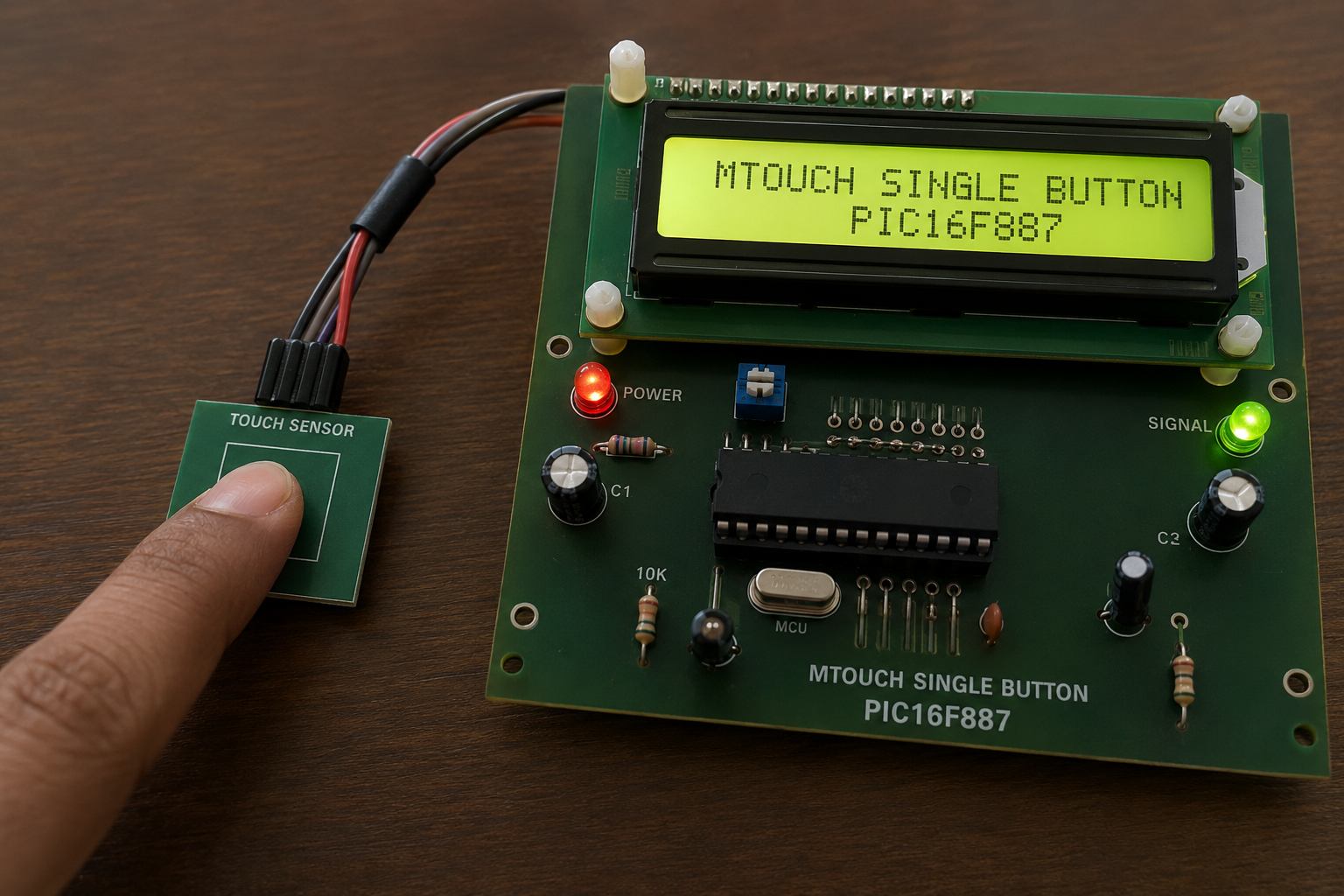
Summary of MTOUCH Single Button using PIC16F887 with Proteus Simulation


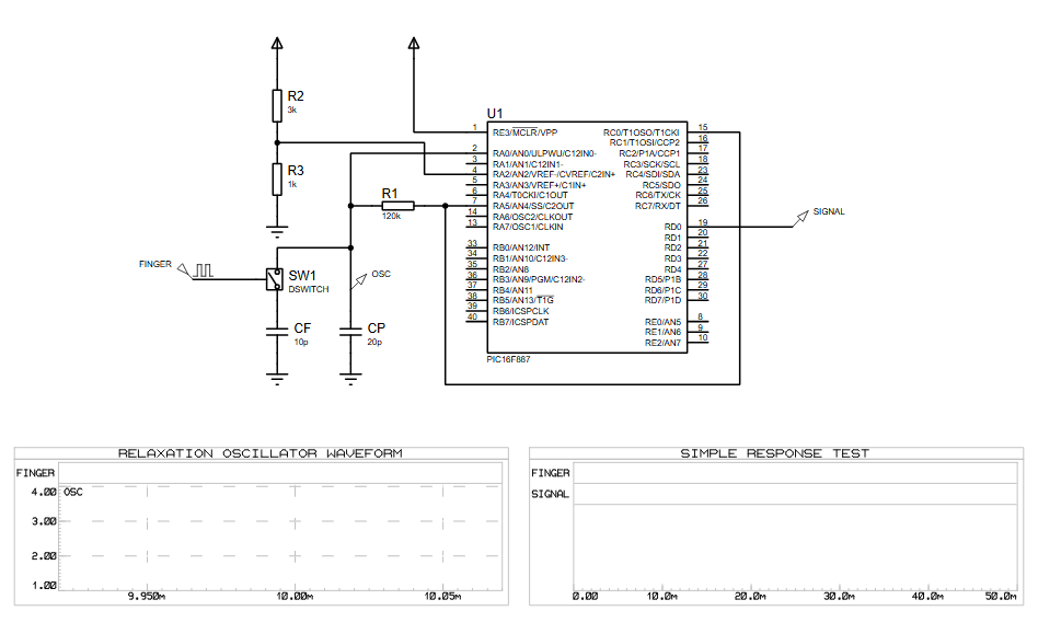
This article details the MTOUCH Single Button project, a capacitive touch sensing system simulated in Proteus using the PIC16F887 microcontroller. It employs a relaxation oscillator technique where touching a sensor pad alters capacitance, changing oscillation frequency to trigger a signal response. The project serves as an educational tool for embedded systems, demonstrating touch interface design with minimal components and real-time waveform monitoring without physical hardware.

Parts used in the MTOUCH Single Button:

  • PIC16F887 Microcontroller
  • Resistor R1 (120kΩ)
  • Resistor R2 (3kΩ)
  • Resistor R3 (1kΩ)
  • Capacitor CF (10pF)
  • Capacitor CP (20pF)
  • Touch Switch / Sensor Pad
  • Signal Output Node
  • Proteus Virtual Oscilloscope / Graph Tools

Introduction

Capacitive touch sensing has become a popular feature in modern embedded systems and DIY electronics projects. This MTOUCH Single Button project demonstrates how a touch-sensitive input can be implemented using the PIC16F887 microcontroller inside a Proteus simulation environment.

The project uses a simple relaxation oscillator technique to detect human touch on a sensor pad and generate a response signal through the microcontroller. This type of microcontroller project is useful for learning touch interfaces, signal sensing, and practical electronics design.

Using Proteus simulation allows developers and students to test the working principle without requiring physical hardware. It is an excellent example of an embedded systems project focused on touch sensing and digital signal processing concepts.

Finger touching PIC16F887 capacitive touch sensor demonstration board

How the Project Works (Overview)

The project is based on a capacitive touch sensing method using a single touch button connected to the PIC16F887 microcontroller.

When a user touches the sensor input labeled FINGER, the capacitance at the input node changes slightly. This affects the frequency characteristics of the oscillator circuit formed by the resistor-capacitor network connected to the microcontroller pins.

The PIC16F887 continuously monitors this oscillation behavior and detects the change caused by touch activity. Once a valid touch is detected, the controller generates an output response on the signal line.

The system demonstrates how capacitive sensing can be implemented with minimal external components in a Proteus simulation setup.

Workflow Explanation

Input Stage

  • The FINGER touch pad acts as the capacitive sensing surface.
  • Touching the pad changes the electrical capacitance.

Oscillator Circuit

  • Resistors R1, R2, R3 and capacitors CF, CP create a relaxation oscillator network.
  • Oscillation frequency varies depending on touch conditions.

Microcontroller Processing

  • The PIC16F887 reads the oscillator response through its input pins.
  • Internal firmware analyzes the signal timing.

Output Response

  • Once a touch is detected, the controller activates the SIGNAL output.
  • The waveform and response can be observed directly in Proteus graphs.

Key Features

  • Single-button capacitive touch sensing
  • PIC16F887 microcontroller-based design
  • Relaxation oscillator touch detection method
  • Proteus VSM simulation support
  • Low external component count
  • Real-time waveform monitoring
  • Embedded systems learning project
  • Practical touch interface implementation

Components Used

  • PIC16F887 Microcontroller
  • Resistors
    • R1 = 120kΩ
    • R2 = 3kΩ
    • R3 = 1kΩ
  • Capacitors
    • CF = 10pF
    • CP = 20pF
  • Touch Switch / Sensor Pad
  • Signal Output Node
  • Proteus Virtual Oscilloscope / Graph Tools

Applications

This type of touch sensing system can be used in:

  • Touch-sensitive switches
  • Home automation systems
  • Smart control panels
  • Consumer electronics
  • DIY electronics projects
  • Embedded systems education
  • Human-machine interface systems
  • Low-cost capacitive sensing devices

Explanation of Code

The firmware running on the PIC16F887 is responsible for monitoring the oscillator behavior generated by the RC network connected to the touch sensor.

The main program continuously measures signal variations caused by changes in capacitance when a finger touches the sensor area. Based on predefined thresholds, the firmware determines whether a valid touch event has occurred.

The project mainly involves:

  • GPIO pin monitoring
  • Oscillator signal measurement
  • Capacitive touch detection logic
  • Signal response generation
  • Timing-based sensing operations

The design demonstrates a practical implementation of capacitive touch sensing in embedded systems without requiring dedicated touch controller hardware.

Proteus Simulation

The Proteus simulation demonstrates the working behavior of the capacitive touch sensing system in real time.

The waveform graph labeled RELAXTION OSCILLATOR WAVEFORM displays oscillator activity generated by the RC sensing network. When the touch sensor is activated, the oscillation behavior changes and the PIC16F887 processes the input accordingly.

The SIMPLE RESPONSE TEST graph can be used to monitor the response signal generated by the microcontroller after touch detection. This allows users to analyze the sensing performance directly inside the Proteus environment.

Conclusion

The MTOUCH Single Button using PIC16F887 with Proteus Simulation project is a simple yet effective demonstration of capacitive touch sensing in embedded systems. It provides valuable hands-on experience with microcontroller programming, oscillator-based sensing, and Proteus simulation analysis.

This project is ideal for students, electronics enthusiasts, and developers interested in learning modern touch interface techniques in DIY electronics and practical microcontroller applications.

Quick Solutions to Questions related to MTOUCH Single Button:

  • How does the project detect human touch?
    Touching the FINGER pad changes electrical capacitance, which alters the frequency of the relaxation oscillator network.
  • What microcontroller is used in this simulation?
    The project uses the PIC16F887 microcontroller to monitor the oscillator and generate output responses.
  • Can this project be tested without physical hardware?
    Yes, the Proteus simulation environment allows developers to test the working principle without requiring physical hardware.
  • Does the oscillator frequency change when touched?
    Yes, the oscillation frequency varies depending on whether the touch conditions are active or inactive.
  • What software tools are used to observe the response?
    Proteus Virtual Oscilloscope and Graph Tools display the RELAXTION OSCILLATOR WAVEFORM and SIMPLE RESPONSE TEST graphs.
  • How does the firmware determine a valid touch event?
    The firmware analyzes signal timing variations based on predefined thresholds to decide if a valid touch has occurred.
  • Is dedicated touch controller hardware required for this design?
    No, the design demonstrates implementation without requiring dedicated touch controller hardware.
  • What happens after a touch is detected by the controller?
    The controller activates the SIGNAL output line to indicate the detection event.

About The Author

Ibrar Ayyub

I am an experienced technical writer holding a Master's degree in computer science from BZU Multan, Pakistan University. With a background spanning various industries, particularly in home automation and engineering, I have honed my skills in crafting clear and concise content. Proficient in leveraging infographics and diagrams, I strive to simplify complex concepts for readers. My strength lies in thorough research and presenting information in a structured and logical format.

Follow Us:
LinkedinTwitter