Summary of MMC/SD Card raw data read with PIC16F887 microcontroller
This article demonstrates reading raw data (bytes and sectors) from an MMC/SD card using a PIC16F887 microcontroller without file systems like FAT. It highlights the RAM limitation preventing full sector writes, suggesting external EEPROM for writing but confirming byte-by-byte reading is feasible. The system uses UART communication via a MAX232 chip to display data on a serial monitor, with voltage regulation provided by an AMS1117 3.3V regulator.
Parts used in the Interfacing MMC/SD card with PIC16F887 project:
- PIC16F887 microcontroller
- SD Card
- AMS1117 3.3V voltage regulator
- 3 x 3.3K ohm resistor
- 3 x 2.2K ohm resistor
- 10K ohm resistor
- 5 x 10uF polarized capacitor
- 100nF ceramic capacitor
- MAX232 chip
- Female COM port
- 5V Power source
- Breadboard
- Jumper wires
This small example shows how to read SD card raw data (bytes, sectors …). SD card raw data means that there is no use of system files like FAT16 or FAT32. Serial monitor is used to display the data after reading it and here the UART protocol is used.
the link below shows a small PIC16F887 MCU UART example:
UART Example for PIC16F887 microcontroller using CCS PIC C compiler
In this project I used the MMC/SD card driver for CCS C compiler which is described in the post at the link below:
MMC/SD Card driver for CCS PIC C compiler
The PIC16F887 MCU has only 368 bytes of data RAM which means that it is not possible to load an entire sector of 512 bytes. That means we can’t write byte or sector correctly with this microcontroller unless an external component is added to the circuit such as external EEPROM which of course slows the writing process. But reading is not like writing, we can read all the SD card data byte by byte.
Hardware Required:
- PIC16F887 microcontroller
- SD Card
- AMS1117 3.3V voltage regulator
- 3 x 3.3K ohm resistor
- 3 x 2.2K ohm resistor
- 10K ohm resistor
- 5 x 10uF polarized capacitor
- 100nF ceramic capacitor
- MAX232 chip
- Female COM port
- 5V Power source
- Breadboard
- Jumper wires
Interfacing SD card with PIC16F887 MCU circuit:
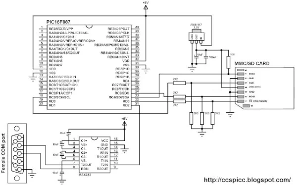
The AMS1117 3.3V voltage regulator is used to supply the SD card with 3.3V. Also 3 voltage dividers are used to step down the 5V which comes from the microcontroller to about 3V which is sufficient for the SD card. Each voltage divider consists of 2K2 and 3K3 resistors.
MAX232 integrated circuit is used to interface the microcontroller with the PC, I connected just one wire (RD2) because I need to transmit data from the SD card to the microcontroller and then from the microcontroller to the PC, there is no need to connect the second wire because I don’t have to send data from the PC to the microcontroller.
Read more: MMC/SD Card raw data read with PIC16F887 microcontroller
- What does this project demonstrate?
This project shows how to read SD card raw data such as bytes and sectors without using file systems like FAT16 or FAT32. - Can the PIC16F887 write entire sectors correctly?
No, because it has only 368 bytes of data RAM, which is insufficient for a 512-byte sector, so writing requires an external component like an EEPROM. - How is the SD card powered in this circuit?
The AMS1117 3.3V voltage regulator is used to supply the SD card with 3.3V. - Why are voltage dividers used in the circuit?
Voltage dividers consisting of 2K2 and 3K3 resistors step down the 5V from the microcontroller to about 3V sufficient for the SD card. - Which chip is used to interface the microcontroller with the PC?
The MAX232 integrated circuit is used to interface the microcontroller with the PC. - How many wires are connected between the MAX232 and the microcontroller?
Just one wire (RD2) is connected because data transmission is only needed from the SD card to the PC. - What protocol is used to display the data after reading?
The UART protocol is used with a serial monitor to display the data. - Is it possible to read all SD card data byte by byte?
Yes, unlike writing, reading can be done all the way through byte by byte despite the RAM limitations.