Summary of Microcontroller measures heart rate through fingertip
The article describes a fingertip heart-rate monitor: an IR LED and photodiode sense blood-volume changes, two cascaded active low-pass op-amp filters (each ~2.5 Hz cutoff, gain ~100) amplify the pulsatile signal to TTL level, and a PIC16F628A microcontroller turns on a BC547-controlled LED/transistor path for 15 seconds to count pulses and multiply by 4 to get bpm.
Parts used in the Fingertip Heart Rate Monitor:
- Infrared LED (IR LED, D1)
- Photodiode (D2)
- Two operational amplifiers configured as active low-pass filters
- 1 µF input coupling capacitors (one for each OpAmp stage)
- LED (pulse indicator)
- BC547 transistor
- PIC16F628A microcontroller
- Resistors and capacitors for filter cutoff and gain (implicit in signal conditioning)
- Power source / battery
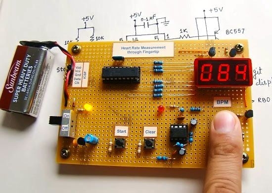
Step 1: Sensor assembly
The sensor unit consists of an infrared light-emitting-diode (IR LED) and a photo diode, placed side by side, and the fingertip is placed over the sensor assembly, as shown below. The IR LED transmits an infrared light into the fingertip, a part of which is reflected back from the blood inside the finger arteries. The photo diode senses the portion of the light that is reflected back. The intensity of reflected light depends upon the blood volume inside the fingertip. So, every time the heart beats the amount of reflected infrared light changes, which can be detected by the photo diode. With a high gain amplifier, this little alteration in the amplitude of the reflected light can be converted into a pulse.
 Step 2: Signal conditioning circuit
The reflected IR signal detected by the photo diode is fed to a signal conditioning circuit that filters the unwanted signals and boost the desired pulse signal. The circuit diagram above shows the IR LED (D1) and the photo diode (D2) along with the signal conditioning circuit made of two stage operational amplifiers configured as active low pass filters. The cut-off frequencies of both the filters are set to about 2.5 Hz, and so it can measure the pulse rate up to 2.5*60 = 150 bpm. The gain of each filter is about 100, which gives the total 2-stage amplification of 10000. This is good enough to convert the weak pulsating signal into a TTL pulse.
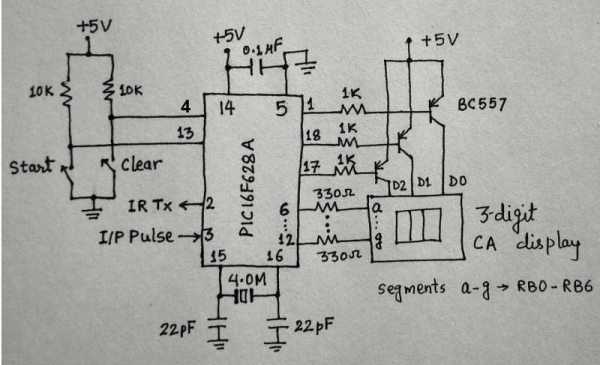 Note that at the input of each OpAmp filter stage, there is a 1 uF capacitor to block any DC component in the signal. At the output is connected a LED that will blink with heart beat. The cathode of LED gets the ground path through the collector of BC547 transistor. In order to save the battery life, the transistor is turned on for 15 seconds by PIC16F628A microcontroller while the measurement is going on. The number of pulses counted within this interval is multiplied by 4 to get actual beats per minutes (bpm).
For more detail: Microcontroller measures heart rate through fingertip
- How does the sensor detect heart beats?
The IR LED transmits infrared light into the fingertip and the photodiode senses variations in reflected light caused by blood volume changes with each heartbeat. - What signal conditioning is used?
Two-stage operational amplifier active low-pass filters with cutoff about 2.5 Hz and gain about 100 per stage are used to filter and amplify the signal. - Why are 1 µF capacitors used at the OpAmp inputs?
They block DC components in the signal at the input of each OpAmp filter stage. - How is the amplified signal turned into a visible pulse?
An LED is connected at the output and blinks with the heartbeat; its cathode gets ground through the BC547 transistor. - How long does the microcontroller enable the transistor for counting?
The PIC16F628A microcontroller turns on the transistor for 15 seconds during measurement. - How is beats per minute (bpm) calculated?
The number of pulses counted in 15 seconds is multiplied by 4 to obtain bpm. - What pulse rate range can be measured?
With a 2.5 Hz cutoff the circuit can measure up to 2.5 * 60 = 150 bpm. - Why is high amplification necessary?
High gain (total ~10000) converts the weak pulsating reflected IR signal into a TTL pulse suitable for counting.