Summary of Metal Detecting with PIC18-Q71 Microcontroller
This article describes a metal detector using PIC18‑Q71 microcontroller CIPs that senses changes in damping of an LC resonant tank caused by eddy currents in nearby metal. A PWM excites the LC tank; an OPAMP peak detector charges an RC timing network; the microcontroller’s comparator and DAC measure RC discharge time to distinguish metallic from non‑metallic objects. R1 protects I/O diodes and startup calibration sets the detection threshold.
Parts used in the Metal Detecting with PIC18-Q71:
- PIC18-Q71 microcontroller (with built-in CIPs: OPAMP, Comparator, DAC, PWM)
- Inductor (tank coil)
- Capacitor (for LC resonant tank)
- Diode (between PWM and tank)
- Current-limiting resistor (R1)
- Resistor and capacitor for RC resonant/timing network
- Optional protective ESD diodes (internal to MCU)
- Power supply for microcontroller and tank drive
Distinguish between metal and non-metallic objects using Core Independent Peripherals (CIPs) with the Metal Detecting with PIC18-Q71 Microcontroller.
Story about Metal Detecting with PIC18-Q71
This application creates a simple proximity metal detector with the Core Independent Peripherals (CIPs) in the PIC18-Q71 family of microcontrollers (MCUs) to differentiate between metallic and non-metallic objects placed near the detector coil. The CIPs are built into the die of the microcontroller to reduce the number of external components needed and the design area, all while increasing the functionality of the device.
Theory of Operation
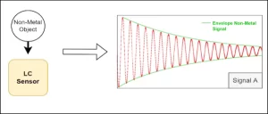
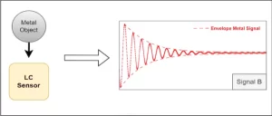
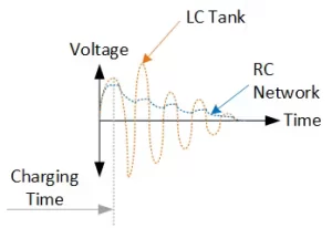
In short, this application works by detecting a change in the damping time of an LC resonant network (composed of an inductor and capacitor in parallel). Metal near the inductor creates eddy currents from the inductor’s magnetic field, which causes the LC network to damp faster than if a non-metallic object (or air) was placed nearby.
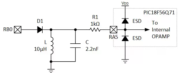
First, let’s look at the LC tank. To generate ringing, a Pulse-Width Modulated (PWM) waveform is applied to the resonant tank. The PWM duty cycle is set to half the period of the resonant frequency, to avoid dissipating excessive power and to increase time for the tank to ring between pulses. The pulses are then passed through a diode to protect the microcontroller I/O and to avoid dissipating the energy applied to the tank. A current-limiting resistor connects the LC tank to one of the Operational Amplifier (OPAMP) inputs on the microcontroller. This resistor (R1) is crucial to the design, as it reduces the current through the diodes to a safe level. Without it, the electro-static discharge (ESD) diodes inside the I/O would normally short the negative pulses to ground, dissipating the energy, potentially damaging the microcontroller. R1 reduces the current through the diodes to a safe level.
Operational Amplifier (OPAMP)
The internal OPAMP of the microcontroller is set up in a unity gain configuration with a peak detector. The peak detector adds an internal diode to the output of the OPAMP, allowing the OPAMP to only drive the output if the RC network is at a lower voltage.
On the output I/O is an RC resonant circuit. Ordinarily, directly driving a capacitor with an OPAMP would not be recommended, but in this case, the circuit is acceptable due to the peak detector configuration.
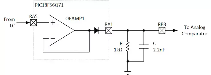
This RC network is charged by the OPAMP and is constantly discharging through the resistor in parallel with the capacitor. As the LC tank resonates, the peaks of the LC resonance cause the OPAMP to momentarily recharge the RC network when the LC voltage is above the RC voltage, which stretches the time out.
Now, to detect metal, the microcontroller uses an internal Analog Comparator (CMP) to measure the discharge time of the RC network to a known voltage set by the Digital-to-Analog Converter (DAC). Discharge time is calibrated on start-up.
- How does the detector distinguish metal from non-metallic objects?
By measuring the faster damping of the LC resonant tank caused by eddy currents in nearby metal, which shortens the LC ringing and changes the RC discharge timing. - What excites the LC resonant tank?
A PWM waveform from the microcontroller, with duty cycle set to half the resonant period, excites the LC tank. - Why is a diode used between the PWM and the tank?
The diode protects the microcontroller I/O and prevents dissipation of energy applied to the tank. - What is the role of R1 in the circuit?
R1 is a current-limiting resistor that reduces current through ESD diodes to a safe level, protecting the microcontroller. - How does the OPAMP contribute to detection?
The internal OPAMP is configured as a unity gain peak detector that recharges the RC timing network when LC peaks exceed the RC voltage, stretching timing for measurement. - How is the RC network used to sense changes?
The RC network is charged by the OPAMP and discharged through a resistor; the microcontroller measures its discharge time to a DAC-set reference using the analog comparator. - What internal peripherals of the PIC18-Q71 are used?
The application uses the OPAMP, Analog Comparator (CMP), Digital-to-Analog Converter (DAC), and PWM Core Independent Peripherals. - Is calibration required?
Yes, discharge time is calibrated on startup to set the detection threshold.