


Summary of Line following robot using PIC16F84
The JavaBot1 is a compact line-following robot designed to navigate tight curves on dry erase boards. It utilizes modified Cirrus CS-70 servos converted into gear motors, controlled via an H-bridge circuit for precise speed and direction. The system employs seven QRB1114 I/R reflective sensors arranged in an inverted V pattern to detect the line, utilizing an LM311 comparator and a 74HCT138 decoder to interface with a PIC16F84 processor.Parts used in the JavaBot1:
- Cirrus CS-70 servos (modified for full rotation)
- H-bridge circuit
- QRB1114 I/R reflective sensors
- LM311 comparator
- 74HCT138 decoder
- PIC16F84 microprocessor
- Current limiting resistors
Design Goal:
The JavaBot1 is a small line following robot designed to follow a black line drawn on a dry erase board. It is designed to follow very tight curves. The software still has lot's of room for improvement but works well as is.
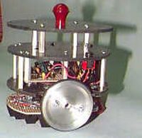
Motive Power:
The JavaBot1 uses 2 Cirrus CS-70 servos that have been modified
for full rotation and have had their controller boards removed to
convert them from servos to gear motors.
Servos are a common motive power for small robots due to their
low cost, ready availability, standardized sizes and the fact that it
only requires 1 bit on your processor to control the motor.
We initially tried this approach but found that the speed control was
very minimal with a finer control needed for this application. The
servo controller boards were then removed and the wires soldered
to the motor terminals and case ground. The motors were then
controlled by an H-bridge circuit to allow direction and speed control
with only 2 processor bits per motor. This is implemented as one bit for
direction and another bit for power/speed control per motor.
Sensors:
In order to follow the line I/R reflective sensors were used to
detect if a line was present or not. The sensors chosen are the
QRB1114 from QT Optoelectronics and have a focal point of
about 1/4 inch. They are available from DIGI-KEY.
Most line followers use 2 or 3 sensors of this type to do their
detection. This works but does not give the ability to follow
lines with very tight turns. An array of seven sensors arranged
in an "inverted V " patternare bolted under the front of the robot
The sensors are wired with all the receivers connected in parallel and
fed to an LM311 comparator to set the threshold trigger level with it's
output fed to a processor bit. The transmitter LEDs are connected
to a 74HCT138 with a current limiting resistor to VCC. This allows
the entire array to use 4 bits for the sensors.
For more detail: Line following robot using PIC16F84
Quick Solutions to Questions related to JavaBot1:
-
What is the primary design goal of the JavaBot1?
To follow a black line drawn on a dry erase board while navigating very tight curves. -
How are the motive power servos modified for this project?
The controller boards are removed from Cirrus CS-70 servos to convert them into gear motors for full rotation. -
Why was the servo controller board removed?
The original setup offered minimal speed control, so removing the board allowed for finer control using an H-bridge. -
Which sensor model is used to detect the line?
The project uses QRB1114 sensors from QT Optoelectronics with a focal point of about 1/4 inch. -
How many sensors are used and how are they arranged?
An array of seven sensors is bolted under the front of the robot in an inverted V pattern. -
What component sets the threshold trigger level for the sensors?
All receiver outputs are connected in parallel and fed to an LM311 comparator to set the threshold. -
How are the transmitter LEDs connected in the sensor array?
The LEDs are connected to a 74HCT138 with a current limiting resistor to VCC. -
What microcontroller processes the sensor data?
The system uses a PIC16F84 processor to control the motors and read sensor inputs.
Related projects
PIC Stepper Motor Controller using PIC16F84A with Proteus Simulation
Introduction Stepper motors are widely used in embedded systems and DIY electronics projects where precise position control is required. This PIC Stepper...
Programmers & ICSP · PIC16F84APIC Musical Doorbell using PIC16F84A with Proteus Simulation
IntroductionThis microcontroller project demonstrates a musical doorbell built around a PIC16F84A and a simple piezo sounder.Using two push buttons, the system allows...
Beginner Tutorials · PIC16C84Exploring the World of PIC Microcontrollers: An Architectural Overview
A Peripheral Interface Microcontroller (PIC), developed by General Instruments Microcontrollers in 1993, operates under software control and is programmed to execute various...
Motors & RoboticsReal-Time CAN-Based Vehicle Monitoring System with PIC MCU
INTRODUCTION The Controller Area Network (CAN) is a robust vehicle communication bus standard that was primarily developed for automobile applications but has...
Motors & RoboticsEasy Way to Learn Robotics Using Microcontrollers: A Beginner’s Guide
The title, "Easy Way to Learn Robotics Using Microcontrollers," promises an accessible entry point for those curious about the exciting world of...
Motors & Robotics · PIC16F877AEfficient Sun-Following Robot: A Solar Tracker with Microcontroller Control
Abstract The impending global challenge of dwindling non-renewable fuel resources underscores the urgency of transitioning towards renewable energy alternatives like solar power....

Ibrar Ayyub
I am an experienced technical writer holding a Master's degree in computer science from BZU Multan, Pakistan University. With a background spanning various industries, particularly in home automation and engineering, I have honed my skills in crafting clear and concise content. Proficient in leveraging infographics and diagrams, I strive to simplify complex concepts for readers. My strength lies in thorough...