Summary of Propeller Clock Mechanically Scanned LED Clock using PIC16C84
This article details a DIY propeller clock that uses a spinning motor and seven LEDs to create a 7x30 LED array illusion via precise timing. It requires mechanical skills, prior electronics experience, and a salvaged motor from a VCR or floppy drive. The project includes downloadable schematics, source code for PIC16C84/16F84 microprocessors, and PCB layouts, all under the GNU General Public License.
Parts used in Propeller Clock Mechanically Scanned LED Clock:
- Motor from a dead VCR, floppy drive, or disk drive
- PIC16C84 or 16F84 microprocessor
- Seven LEDs
- Programmer for PIC16C84 or 16F84
- Printed Circuit Board (PCB)
This is the first clock I ever built. I’ve built a few LED signs, but they get boring because I already know the message.
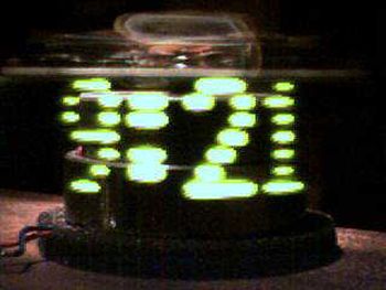
How this clock works:
A motor spins the “propeller”, and a small microprocessor keeps track of time and changes the pattern on seven LEDs with exact timing to simulate a 7 by 30 array of LEDs. It is an illusion, but it works nicely.
If you want to build this clock, you will need a few things, including:
Skill with motors and mechanical things.
Prior electronic experience.
A dead VCR or floppy drive or other source of a suitable motor and miscellaneous parts.
A programmer that will program a PIC16C84 or 16F84 microprocessor.
I have provided (almost)everything else:
The Next Page with drawings and plans.
Download:
mclock.txt A full description how to build it.
mclkpart.txt The parts list.
mclock8.asm The source code in Microchip MPASM format.
mclock8.hex The hex code ready to load into a PIC16C84 or 16F84 chip.
mclksch2.gif A large and very readable schematic diagram.
mclkmoto.gif A drawing of the modifications to the motor.
If you can’t get that kind of motor, you can use the motor from an old disk drive. This page has a lot of pictures and will take some time to load. If you use a disk drive motor or any other DC motor with brushes 180 degrees apart, you’ll need the slightly revised code:
Download:
mclockt3.asm The source code.
mclockt3.hex The hex code ready to put in a chip.
If you don’t have any way to put the program into a PIC 16C84 or 16F84 chip, you can build your own programmer.
Printed Circuit Board Layout for a version of the clock.
License:
The hardware design and software are covered under the GNU General Public License.
For more detail: Propeller Clock Mechanically Scanned LED Clock using PIC16C84
- How does this clock work?
A motor spins a propeller while a microprocessor changes the pattern on seven LEDs with exact timing to simulate a 7 by 30 array of LEDs. - What skills are needed to build this clock?
You need skill with motors and mechanical things as well as prior electronic experience. - Where can I get a suitable motor for the project?
You can use a motor from a dead VCR, floppy drive, or other similar source. - Can I use a disk drive motor instead of a VCR motor?
Yes, you can use a motor from an old disk drive or any DC motor with brushes 180 degrees apart. - Which microprocessor is required for this project?
The project uses a PIC16C84 or 16F84 microprocessor. - Is there a programmer available for the microprocessor?
You will need a programmer that can program a PIC16C84 or 16F84, or you can build your own if you do not have one. - What files are provided for building the clock?
Downloads include mclock.txt, mclkpart.txt, mclock8.asm, mclock8.hex, mclksch2.gif, and mclkmoto.gif. - Under what license are the hardware design and software covered?
The hardware design and software are covered under the GNU General Public License.