Summary of LED Persistence of Vision Display
This article details the electrical system for a Persistence of Vision (POV) LED display using a single PIC 18F2455 microcontroller. The timing mechanism utilizes a reed switch and magnet to measure rotation speed, avoiding noise issues associated with Hall effect sensors. The LED control system manages 40 LEDs across four columns and ten rows by cycling through ground connections via n-type MOSFETs. A custom two-layer PCB was designed to ensure structural integrity.
Parts used in the LED Persistence of Vision Display:
- PIC 18F2455 microcontroller
- Reed switch
- Magnet
- Hall effect sensor
- 40 LEDs
- n-type MOSFET transistor
- L-connector
- PCB from Express PCB
Electrical
The main components of the electrical system were the timing system and the LED control system for 40 LEDs using a single PIC. A schematic of the system is shown below (click for larger view):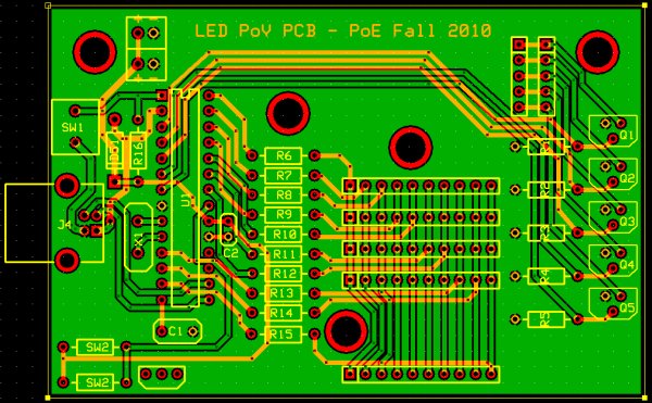
timing
In order to time the display properly to achieve persistence of vision, the PIC needs to record the time between successive rotations. To do this in our project, we investigated various magnetic sensors. In the end, we decided to control timing with a reed switch and magnet (we were originally using a Hall effect sensor). The Hall effect sensor was so sensitive to the magnet that it was susceptible to noise and showed an oscillating signal when we measured it with an oscilloscope. The reed switch is slower, so the signal was smooth and without noise. Nevertheless, we encountered issues potentially due to contact bounce which interfered with the performance of the switch. We put the magnet onto an L-connector on one side of the mechanical system and soldered the reed switch onto the PCB so that once every rotation it passed underneath the magnet. When the magnet is above the reed switch, the two leads inside it connect, and voltage can briefly pass through the switch to port RB0 on the PIC.
LED control
In order to control 40 LEDs with a single PIC 18F2455 microcontroller, we broke the LEDs into a system of four columns containing 10 LED rows. Each of the 10 LEDs in a column was connected to a pin on the PIC. The grounds of all LEDs in a column were connected, with ground controlled by a n-type MOSFET transistor. Only when the input to the transistor was set high was a given column of LEDs grounded; we were able to achieve the semblance of a constant display by quickly cycling between which LED posts are controlled. The circuit diagram is shown above.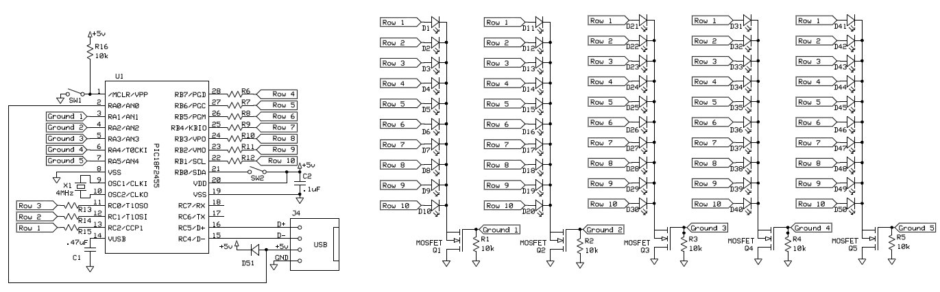
implementation
To ensure that the electrical system was sturdy, we designed and ordered a PCB for the circuitry from Express PCB. The layout is shown below, with component IDs correlating with those in the schematic above.
Two-layer PCB layout for system (dimensions: 3.5 x 2.8 inches)
For more detail: LED Persistence of Vision Display
- Why was a reed switch chosen over a Hall effect sensor?
The Hall effect sensor was too sensitive to noise and produced an oscillating signal, whereas the reed switch provided a smooth signal. - How does the timing system record rotation time?
The PIC records the time between successive rotations when a magnet passes over a reed switch connected to port RB0. - What issue was encountered with the reed switch?
The team encountered potential issues due to contact bounce which interfered with the switch performance. - How are the 40 LEDs organized in the circuit?
The LEDs are broken into a system of four columns containing 10 LED rows each. - How is the ground for each column controlled?
The grounds are connected to an n-type MOSFET transistor that only allows current when the input is set high. - How is the constant display effect achieved?
The system achieves this by quickly cycling between which LED posts are grounded to create persistence of vision. - What material was used to build the sturdy electrical system?
A custom two-layer PCB designed and ordered from Express PCB was used. - What are the dimensions of the PCB layout?
The PCB layout measures 3.5 inches by 2.8 inches.