Summary of LED Microcontroller Debug Module using PIC18F4420
The Microcontroller Debug Module (MDM) simplifies debugging by relocating the MCU away from the breadboard via a 40-pin ribbon cable. It uses 74LS541 drivers to illuminate LEDs for each data port, allowing real-time state monitoring without circuit modification. Designed primarily for PIC18 family chips, it features an onboard oscillator, ICSP header, and DIP switches to manage LED outputs and prevent interference with analog inputs or ADC readings.
Parts used in the Microcontroller Debug Module:
- Microcontroller (MCU)
- 40-pin ribbon cable
- Small PCB substitute board
- 74LS541 8-bit Line Driver ICs
- Indicator LEDs (Red and Green)
- PIC18 family microcontrollers (28 and 40 pin variants)
- J2 40-pin PIC socket
- J8 28-pin PIC socket
- 20x2 IDE cable connection (J3-J6)
- Standalone configuration header (J7)
- DIP switch bank (DSW1)
- Onboard oscillator
- ICSP header
- Switch SW1
When it comes to debugging a microcontroller circuit, there aren’t a lot of simple options. Since a microcontroller circuit might have multiple things going on at the same time, measuring voltages with a DMM isn’t an option. Using an computerized In-Circuit-Debugger solution is expensive and elaborate, and time-consuming to set up. People often resort to connecting banks of LEDs to the circuit, but this also takes time and if wired incorrectly, might mislead you about the issues you are trying to solve.
Enter the Microcontroller Debug Module (MDM). It is a device which simply transplants the microcontroller (MCU) to a separate unit, away from the breadboard. It is connected by a 40-pin ribbon cable to a small PCB which takes the place of the MCU on the breadboard, transposing each pin directly. No circuit modifications are required for the operation of the MDM. On the module are 74LS541 8-bit Line Driver ICs which drives indicator LEDs for each of the 8 bits on each of the data ports on the MCU. This chip delivers current for the LEDs without affecting the pin of the MCU itself. The pin and the breadboard circuit have no idea the chip is there.
My microcontrollers of choice are PIC18 family 28 and 40 pin PICs which I have designed this unit to be pin-compatible for. Your unit can be designed for Arduino Atmel chips or any MCU you wish to use.
This Instructable is mostly intended to inspire ideas and some circuit pieces to help you develop a MDM for your own favorite family of MCU.
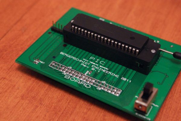
Also Please note the schematic and board layout are regarding Revision 0.3, it is far more advanced and has numerous corrections/features added to it, compared to Rev 0.1, which is photographed.
Step 1: Schematic Design
The schematic is large but fairly simple and can be broken down into some smaller parts.
- J2 is the 40-pin PIC socket, which connects pin-for-pin to the 40-pin IDE connector
- J8 is the 28-pin PIC socket, which will rest in between the 40-pin socket
- J3-J6 are arranged to form a 20×2 IDE cable connection for connecting the MDM to the PIC substitute board
- J7 is a header for running the MDM in a stand-alone configuration without power from the breadboard circuit
Each port has a 74LS541 connected to it which buffers and supplies current for 16 LEDs. A red LED has its cathode connected to the output pin and its anode ultimately connected to a +5V rail, and a green LED has its anode connected to the same output pin with its cathode connected to ground. The result is that when the PIC pin goes high, the corresponding 74LS541 pin does the same. When the pin is high the red LED has +5V on both sides of it, and thus will not light, but the green LED has +5V of potential on it now, and will light. When the pin is low then the red LED now has +5V of potential across it, and the green LED has GND on both sides of it and will not light. If the pin is rapidly switching from high to low, it will appear as if both LEDs are illuminated. Both LEDs would appear lit only in the event that the MCU pin is rapidly changing states, or if the 74LM541 has been disabled.
DSW1 is a DIP switch bank that allows the user to disable or enable the LED output ports if they so wish to. It will reduce the brightness of the port LEDs if you are not using that port for anything, or if the port is being used as an analog input port. When the pin is Tri-state then both LEDs will light up at 50% brightness. Due to limitations of the 74LS541, when the MCU pin is displaying tri-state, it will display as high. The only time that the output of the 74LS541 will go tri-state is when the enable/disable switch for that chip is enabled.
An oscillator is included on the board, and I recommend it be used because the crystal should be as close to the MCU as possible, and it is not a good idea for it to have to go through a ribbon cable to get there. It might also cause unwanted noise in the rest of the circuit and could affect ADC readings.
an ICSP header is included on the board, and can be enabled/disabled from the MCU pins with SW1.
Please press the “i” symbol at the top corner of each image to view it in full, readable resolution. Thank you
For more detail: LED Microcontroller Debug Module using PIC18F4420
- How does the MDM allow debugging without modifying the original circuit?
The device transplants the MCU to a separate unit connected by a ribbon cable, requiring no circuit modifications on the breadboard. - What component drives the indicator LEDs for the data ports?
74LS541 8-bit Line Driver ICs are used to drive the LEDs without affecting the MCU pins. - Can this module be designed for Arduino Atmel chips?
Yes, while designed for PIC18, the unit can be adapted for Arduino Atmel chips or any other MCU family. - Why is an onboard oscillator recommended over using the external crystal?
An onboard oscillator prevents noise issues and ensures the crystal remains close to the MCU, avoiding signal degradation through the ribbon cable. - What happens when an MCU pin is rapidly switching states?
Both the red and green LEDs will appear illuminated because the human eye perceives the rapid switching as a continuous light. - How can users reduce brightness or disable specific port LEDs?
A DIP switch bank (DSW1) allows users to enable or disable the LED output ports individually. - What occurs if a pin is in a Tri-state condition?
Due to 74LS541 limitations, a Tri-state pin displays as high, causing both LEDs to light up at 50% brightness. - Is the ICSP header always active on the board?
No, the ICSP header can be enabled or disabled from the MCU pins using switch SW1.