LED Infinity Mirror Controller, 32 LEDs, Multiple Patterns
UPDATE: This kit is discontinued please see the new version, 8 Channel LED Controller v.3, the development files are still available to build this version.
As simple a circuit as can be. A 12F675 controls a high-power shift register, which in turn controls up to 48 LEDs at 20ma per, (~120mA per channel) in 8 channels(groups),
Software controlled patterns create seamless effects from group to group. With 4-state greyscale ( 4 states of LED of brightness ) a vast amount of patterns/effects are possible.
It was designed to go along with my 8″x8″ 32 LED Infinity Mirrors.
A Gallery of all my Infinity Mirrors
A single momentary-pushbutton cycles through the programmed patterns. Comes loaded with 5 patterns, and the ability to add more through re-writing the firmware.
Kits, Including 32 LEDs, colors buyer’s choice, can be bought from my store at www.ChromationSystems.com
More Updates and Info will be Posted to the 8 Channel LED Controller Webpage
The Eagle Schematics, PCB layout, and Source Code in Assembly can be purchased all together in a Developer Package.
UPDATE: Code in ASM is available for download below, or on the Main Website
The Schematic, HEX File, and Datasheet are in the ZIP below.
DISCLAIMER: Recreate this project at your own risk.
Parts
UPDATE: This kit is discontinued please see the new version, 8 Channel LED Controller v.3,
To Purchase a Full Kit with all the parts, including 32 5mm LEDs. Visit my Store
Also Available with no LEDs Here
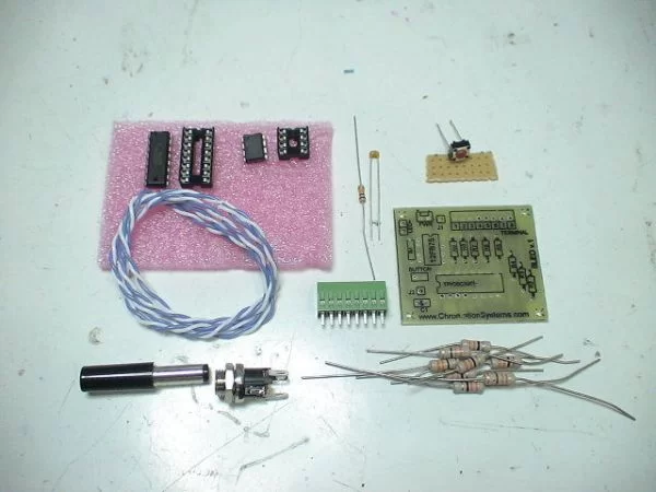
Layout all the Parts:
– programmed 12F675 Buy One
– 8 pin socket
– PCB Buy One
– 8 Position Screw-Down Terminal, with 0.1″ (DIP) spacing
– TPIC6C596, high power shift register
– 0.1uf Capacitor
– 16 pin socket
– 10k 1/4w resistor (Brown, Black, Orange)
– 8 resistors, value depends on LED Color Approx: 20 – 40 ohm
– 32 LEDs, choice of colors
– board mount momentary push-button ( kit comes with an extra panel-mount button )
– scrap of perfboard
– Dual-Strand wire, 22 ga
– ~2″ of solid strand for jumping
– 5 volt, 600ma+ PSU Optional: with barrel Jack Buy One
Optional: ( supplied with the Kit )
– panel mount DC jack
– PSU with correct DC Plug
Tools:
– Soldering Iron
Resistors, Capacitor & Sockets
Place the resistors first.
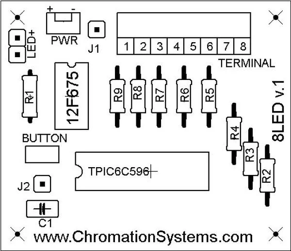
– R1 is a 10kohm (Brown, Black, Orange), 1/4w, it is the pull-up for the push-button switch
– R2 – R9 are the resistors for the LEDs.
– The values of R2-R9 vary depending on the Color of the LEDs and the amount per channel.
– Depending the resistors may or may not sit flat on the PCB, if they are to big, just place them in like in the images below. Flip every other one so the leads are next to each other.
Place the Capacitor C1 next.
– It is not polarized and can be placed in either way.
Sockets are last, be careful placing them. Make sure all the leads get into their correct hole.
There is a notch in the sockets that should line up with the image on the top-side illustration.
Solder them in securely and watch for solder bridges between pins.
For more detail: LED Infinity Mirror Controller, 32 LEDs, Multiple Patterns using PIC12F675


