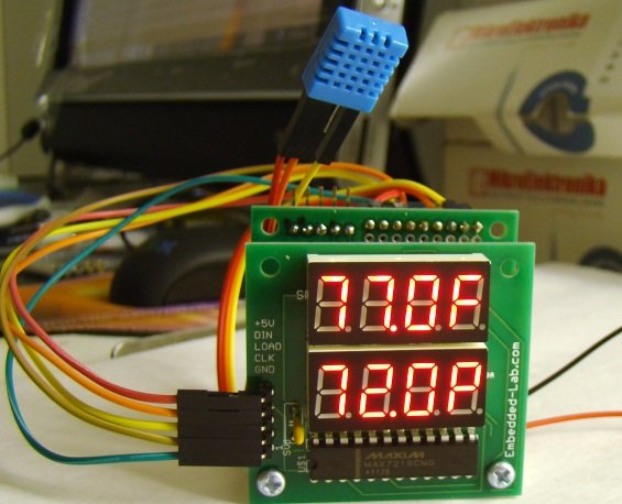
The objective of this project is to illustrate a technique of implementing adaptive brightness control to Smart TrH Display and seven segment LED displays. It consists of a closed loop system that continuously assesses ambient light condition using an inexpensive light-dependent resistor (LDR) and uses that information to adjust the brightness of the display. For the proof of concept, the technique is applied to construct a digital temperature and relative humidity meter that adapts the brightness of the seven segment LED displays to the surrounding lighting conditions. There are 8 seven segment LED displays used in this project and they are all driven by one MAX7219 chip. The ambient temperature and relative humidity are measured using the DHT11 sensor. The microcontroller used in this project is PIC12F683, which is a low-pin-count (8) device from 8-bit PIC microcontroller family. Auto-adjusting the brightness of the seven-segment LED display with surrounding illumination enhances the readability in all ambient lighting conditions.

Theory and circuit setup
Many smartphones, HDTVs, PDAs, tablets, and computer screens now come with an automatic brightness control that aims to conserve power as well as to make the display easier to see in a broad range of illumination conditions. This feature basically dims the display screen in a dark environment and brightens it when the ambient light level is higher. The brighter screen helps to counteract the effects of glare from ambient light and also takes into account for the decreased sensitivity of human eyes to brightness as the ambient light level increases.
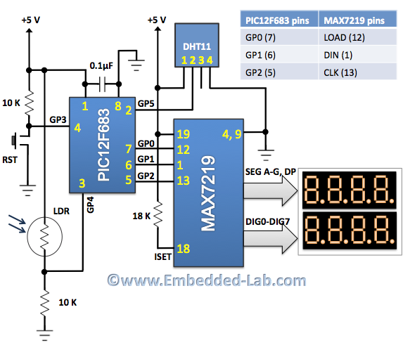
An automatic brightness adjustment is basically a closed loop system that has the capability to assess ambient light and adjust the brightness of the display accordingly. In our project, a general purpose LDR and a fixed value resistor (10K) are connected in series between the power supply and ground pins to create a voltage dividing network, as shown in the circuit diagram below. The resistance of a typical LDR is less than 1 K? under bright lighting condition. Its resistance could go up to several hundred K? under extremely dark condition. Therefore, the voltage across the 10K resistor increases proportionally with the surrounding illumination. For the given setup, the voltage across the 10K resistor can vary from 0.1V (under dark condition) to over 4.0V (under very bright illumination). The PIC12F683 microcontroller reads this analog voltage through its AN3 (GP4) ADC channel and then sends out appropriate signals to the MAX7219 display driver to adjust the brightness of the seven segment LED displays.

The MAX7219 chip provides a serial interface to drive 7-segment LED displays (common-cathode type) up to 8 digits and requires only 3 I/O pins from microcontroller. Included on the chip are a BCD decoder, multiplex scan circuitry, segment and digit drivers, and an 8×8 static RAM to store the digit values. The segment current for all LEDs is set through only one external resistor connected between the ISET pin and power supply. However, the device also provides a digital control of the display brightness (16 steps from minimum to maximum) through an internal pulse-width modulator. To learn more about the MAX7219 device, read my previous article Serial 4-digit seven-segment LED display. In this project, the GP0, GP1, and GP2 I/O pins of PIC12F683 are used to drive LOAD, DIN, and CLK signal lines of the MAX7219.
For more detail: Temperature and relative humidity display with adaptive brightness control

