Summary of Lecture 45 : PIC Serial Communication using Serial Peripheral Interface (SPI)
This experiment establishes serial communication between two PIC16F877A microcontrollers using the Serial Peripheral Interface (SPI). The master reads 8-bit digital input from Port-B and transmits it to the slave, which outputs the value to its own Port-B. Communication utilizes three lines: SDO, SDI, and SCK. The master controls the clock and initiates transmission via the SSPBUF register, while the slave uses interrupts to receive data and update its output port.
Parts used in the PIC16F877A SPI Communication Project:
- PIC16F877A Microcontroller (Master)
- PIC16F877A Microcontroller (Slave)
- Port-B Input (Master)
- Serial Data Out (SDO)
- Serial Data In (SDI)
- Serial Clock (SCK)
- SSPCON Register
- SSPBUF Register
- SSPIF Flag
Objective
To establish serial communication between two PIC16F877A microcontrollers
| Description |
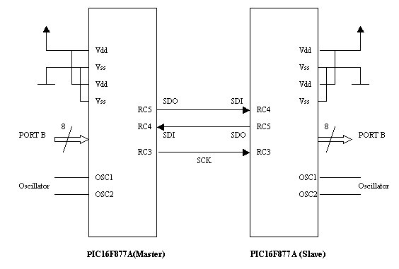
| In this experiment, 8-bit digital input is applied at Port-B to one of the PIC16F877A microcontroller which acts as a master in serial communication. The input value is transmitted by the master serially via Serial Peripheral Interface (SPI) to the second PIC16F877A microcontroller, which acts as a slave. The slave then outputs the value to its Port-B. Following three lines are used for serial communication |
|
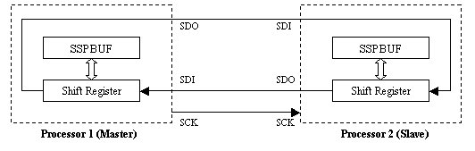
The SDO for master acts as SDI for slave and vice-versa. Serial clock is invariably provided by the master. The SPI communication settings are done using SSPCON register.
|
| Transmission is initiated by the Master by writing to the SSPBUF register. When transfer is complete, Synchronous Serial Port Interface Flag (SSPIF) will be set. This can cause an interrupt if peripheral interrupt is enabled. |
Assembly Code
|
|
| Mainline: |
|
|
|
|
Mainline: bsf STATUS, RP0 ; Bank 1
|
| loop: goto loop ; Infinite loop |
|
For more detail: Lecture 45 PIC Serial Communication using Serial Peripheral Interface (SPI) Schematic
- What is the objective of this experiment?
To establish serial communication between two PIC16F877A microcontrollers. - How does the master initiate transmission?
The master initiates transmission by writing to the SSPBUF register. - Which lines are used for serial communication?
The project uses Serial Data Out, Serial Data In, and Serial Clock. - Does the slave provide the serial clock?
No, the serial clock is invariably provided by the master. - What happens when the transfer is complete?
The Synchronous Serial Port Interface Flag will be set. - Can the completion of a transfer cause an interrupt?
Yes, this can cause an interrupt if peripheral interrupt is enabled. - What value is transmitted by the master?
The master transmits the 8-bit digital input value applied at Port-B. - Where does the slave send the received value?
The slave outputs the value to its Port-B.