Summary of LEARN HARDWARE FIRMWARE AND SOFTWARE DESIGN – BRIEF DESCRIPTION
This article introduces the 5th edition of LHFSD, an educational manual for beginners in hardware design, firmware, and software development. It details the construction of the LHFSD-HCK (Hardware Companion Kit), which can be built on a PCB or breadboard. The kit comprises modular components including power supplies, oscillators, communication interfaces like RS232 and SPI, various I/O modules, sensors, and a dsPIC microcontroller, all designed to facilitate step-by-step learning.
Parts used in the LHFSD-Hardware Companion Kit:
- Power supply module with unregulated +9V and regulated +5V DC
- Oscillator circuit using a ceramic resonator or crystal oscillator
- ICD2 programming interface with RJ-45/6-6 female connector
- RS232 serial communications module using MAX232N IC or discrete components
- Discrete I/O modules for buttons, LEDs, and buzzer
- Serialized I/O modules working over a custom SPI Bus
- Programmable digital potentiometer functioning as an 8-bit DAC via SPI
- Bargraph module using eight comparator Operational Amplifiers and nine LEDs
- Seven Segments three-number LED display using multiplexing and Shift-Registers
- Visual and audio indicators for testing and debugging
- Temperature sensor analog channel
- Linear potentiometer analog channel
- Universal unipolar/bipolar stepper driver module
- Interface connectors for extended functionality
- SPI Bus employing standard logic ICs
- dsPIC30F4011 or dsPIC30F3011 microcontroller
Edition 5 of LHFSD [ISBN 978 606 92185 32] has been specifically designed to become an educational/pedagogical manual for teachers, instructors, and also for ordinary citizens. Have no fear, dear readers: LHFSD is still addressed to beginners, since EVERYTHING starts from a white page, and then things are developed/explained only gradually [and logically], step by step.
Our book continues to deliver exactly as the title says: the readers will learn hardware design, plus firmware and software development! In addition to being a practical project explained in sharp/complete details, each chapter in LSEG5 contains additional simple practical exercises/applications to wade the readers gently throughout the HFS design work. On this Internet page there is a summary presentation of the main parts in LHFSD 5th edition.
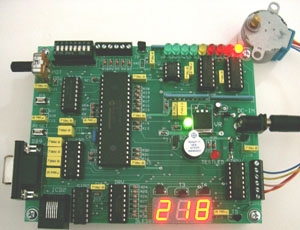 Hardware Design starts from an empty Schematic page, then it builds up gradually the LHFSD-HCK [Hardware Companion Kit]. The novelty in the 5th edition is that it advises the readers to build (alternatively) the LHFSD-HCK kit on a breadboard, instead of a PCB. Things are this way.
Some readers may decide to become perfectly groomed hardware designers; therefore they should build the LHFSD-HCK PCB as it is explained in minute details in our book. However, other readers may prefer to train mostly as firmware and/or software developers. For them, it is advisable to build LHFSD-HCK on a breadboard instead [or on any material that stands to solder temperature]. Note that building LHFSD-HCK is mandatory in order to continue working with the firmware and software development parts in LHFSD5.
LHFSD-HCK has a fair degree of moderate hardware complexity, in order to help beginners most. Consequently, the hardware design work is divided into “modules”, and each hardware-module is explained in sharp details, functionally. Fact is, the Hardware Design part is the easiest one to accomplish!
1. a power supply module having two power levels: unregulated +9V, and regulated +5V DC;
2. an oscillator circuit using a ceramic resonator (the crystal oscillator version is also presented);
3. the ICD2 programming interface using a standard RJ-45/6-6 female connector;
4. the RS232 serial communications module working over USB is presented in 2 versions: using the standard MAX232N IC; plus via a custom RS232 hardware driver built out of discrete components;
 5. a few discrete I/O modules for buttons, leds, buzzer, etc.;
6. a few serialized I/O modules working over a custom SPI Bus–this last application is extremely important!
7. a programmable digital potentiometer working as an 8 bits Digital to Analog Converter controlled via the SPI Bus;
8. a Bargraph module using eight comparator Operational Amplifiers, and controlling an array of nine leds;
9. one Seven Segments three numbers led display using multiplexing, Shift-Registers, and the SPI Bus;
10. visual and audio indicators needed for testing and debugging;
11. one temperature sensor analog channel;
12. one linear potentiometer analog channel;
13. an universal unipolar/bipolar stepper driver module for steppers of 9-12V, and 20-200mA;
14. interface connectors for extended functionality;
15. the SPI Bus employing standard logic ICs–this is one of the most important lessons in hardware and firmware programming;
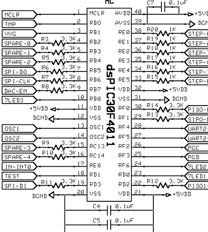
16. the microcontroller dsPIC30F4011/dsPIC30F3011.
For more detail: LEARN HARDWARE FIRMWARE AND SOFTWARE DESIGN – BRIEF DESCRIPTION
- Who is the intended audience for LHFSD 5th edition?
The book is designed for teachers, instructors, ordinary citizens, and beginners starting from a white page. - What skills will readers learn from this book?
Readers will learn hardware design, plus firmware and software development. - Can the LHFSD-HCK be built on a breadboard?
Yes, the 5th edition advises building the kit on a breadboard or any material that stands solder temperature. - Is building the hardware kit mandatory for the rest of the course?
Yes, building the LHFSD-HCK is mandatory to continue working with the firmware and software development parts. - How many power levels does the power supply module provide?
The module provides two power levels: unregulated +9V and regulated +5V DC. - What types of connectors are used for the ICD2 programming interface?
The interface uses a standard RJ-45/6-6 female connector. - What is the purpose of the programmable digital potentiometer in this project?
It works as an 8 bits Digital to Analog Converter controlled via the SPI Bus. - Which microcontrollers are supported by the LHFSD-HCK?
The kit supports the dsPIC30F4011 and dsPIC30F3011 microcontrollers.