Summary of LCD SWR METER CIRCUIT PIC16F877
Summary: An SWR meter using a PIC16F877 microcontroller displays forward, reflected power, SWR, and peak info on a 2×16 LCD. The PCB-based design supports 1–30 MHz, 5–100 W range, SSB peak indication, two-button interface, SWR warning/alarm LEDs, and includes C source libraries (adc.c, lcd8.c, swrm.c, timers) plus two HEX files for PIC16F877/16F877A.
Parts used in the SWR Meter Circuit PIC16F877:
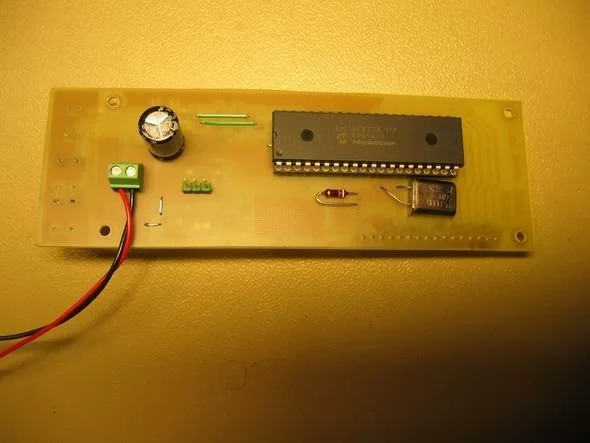
- PIC16F877 or PIC16F877A microcontroller
- 2×16 character LCD display
- PCB (printed circuit board)
- Directional coupler or RF sensing network for forward and reflected detection
- ADC circuitry/components (as referenced by adc.c)
- Timing components (as referenced by timers library)
- Two push buttons for user interface
- SWR warning LED
- Alarm LED
- Power supply components suitable for the circuit
- Passive components (resistors, capacitors, inductors) for RF and signal conditioning
- Hex files and C source code files (adc.c, lcd8.c, swrm.c, timers) for programming
SWR meter circuit pic16f877 microcontroller with lcd display displays the information on a printed circuit board with 2 × 16, schema diagrams in the C source code library files (adc. c, lcd8 c, swrm…. Electronics Projects, LCD SWR Meter Circuit PIC16F877 “microchip projects, microcontroller projects, pic16f877 projects, “
SWR meter circuit pic16f877 microcontroller with lcd display displays the information on a printed circuit board with 2 × 16, schema diagrams in the C source code library files (adc. c, lcd8 c, swrm. c, timers), and I have 2 different hex code for 16f877a 16f877
SWR METER CIRCUIT FEATURES
Power range 5-100W
Frequency range of 1-30 MHz
SSB operation for the Peak indicator
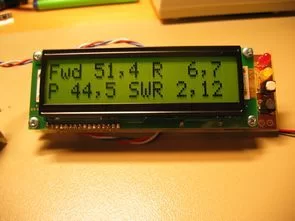
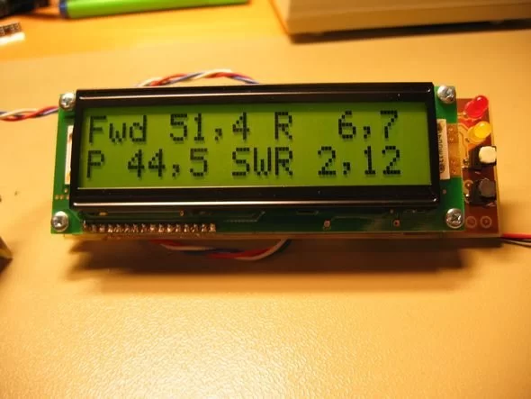
Forward, backward, power and SWR representation
Simple two-button interface
SWR warning and alarm LEDs
Source: LCD SWR METER CIRCUIT Alternatif link: lcd-swr-meter-circuit-pic16f877.rar
- What frequency range does the SWR meter support?
The article states a frequency range of 1-30 MHz. - What power range can the SWR meter measure?
The meter covers a power range of 5-100W. - Does the meter indicate SSB peaks?
Yes, it supports SSB operation for the Peak indicator. - What information is displayed on the LCD?
The LCD displays forward, backward (reflected), power, and SWR representation. - How many buttons are used for user interface?
The design uses a simple two-button interface. - Are there warning or alarm indicators for SWR?
Yes, the circuit includes SWR warning and alarm LEDs. - Which source code files are provided with the project?
The article lists C source/library files: adc.c, lcd8.c, swrm.c, and timers. - Are HEX files available for programming the PIC?
Yes, two different HEX files are provided for PIC16F877A and PIC16F877. - Is the project built on a printed circuit board?
Yes, the information is displayed on a printed circuit board with a 2×16 LCD.