Summary of IR Digital Thermostat for FAN
This circuit monitors temperature in Celsius using an AT89C51 microcontroller and LM35 sensor. It displays readings on an LCD, triggers an alarm at 40°C, and activates a fan via a relay. Users can control three relays and the alarm using IR remote keys (1–4). An ADC0804 converts analog signals to digital for processing, while ULN2003 drives relays safely. A 7805 regulator powers the system, and an LM555 timer drives the buzzer.
Parts used in the IR Digital Thermostat:
- AT89C51 microcontroller
- LM35 temperature sensor
- ADC0804 analog to digital converter
- Alphanumeric LCD screen
- ULN2003 chip
- Relays
- Fan
- 7805 voltage regulator
- 7808 voltage regulator
- Buzzer
- LM555 timer/Oscillator chip
- Philips TV IR remote
Introduction
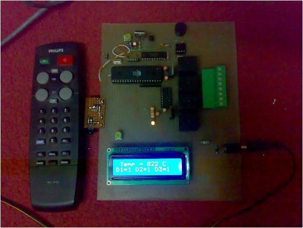
This circuit measures temperature in Celsius scale and displays it on an alphanumeric LCD screen
When temperature rise to 40 C an alarm is activated and at the same time a relay is also activated which
drives a fan to keep the temperature at a level.
Another feature of this circuit is that you can use the keys “1,2,3,4” of a Philips TV IR remote to turn on or off three relays, The key ‘4’ is used to turn on or off the over temperature alarm.
 Hardware
The brain of this circuit is AT89C51 microcontroller. LM35 is a 3 pin chip which is easily available in TO-92
package. LM35 can sense temperature from 0 C to 100 C but it gives analogue output the microcontroller does not understand analogue data, so ADC0804 (analogue to digital converter) is used to convert it to digital form.
This digital data is given to port 1 of microcontroller. (See the circuit diagram) this data is processed by microcontroller and temperature is displayed on lcd connected to port 2.The control pins of lcd are connected to port 0. port 0 also controls the relays and alarm.
The ULN2003 chip is used to drive the relays because the microcontroller pins don’t have enough current to drive them. so relays cant be connected to microcontroller pins directly further more the relays are inductive load and reverse current is generated in them. Pin 1 to 7 are the inputs and 10to 16 are respective outputs. Pin 8 is ground and pin 9 is connected to the output of 7808 voltage regulator.
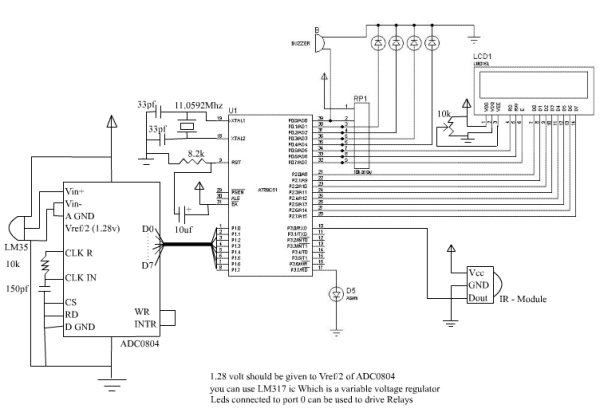 The 7805 voltage regulator drives rest of the circuit. I used a standard buzzer driven by LM555 timer/Oscillator chip. The chip is wired as a monostable multivibrator and at its output (i.e. pin no 3) a buzzer is connected.
For more detail: IR Digital Thermostat for FAN
- How does the circuit detect temperature?
The LM35 sensor senses temperature from 0 C to 100 C and provides an analog output. - What component converts analog data to digital?
The ADC0804 is used to convert the analog output from the LM35 into digital form. - When is the alarm activated?
The alarm is activated when the temperature rises to 40 C. - Which keys are used to control the relays?
The keys 1, 2, and 3 of a Philips TV IR remote turn on or off three relays. - What is the function of key 4 on the remote?
Key 4 is used to turn on or off the over temperature alarm. - Why is the ULN2003 chip used?
The ULN2003 drives the relays because microcontroller pins lack sufficient current and cannot handle reverse current from inductive loads. - How is the buzzer driven?
A standard buzzer is driven by the LM555 timer wired as a monostable multivibrator. - Which voltage regulators power the circuit?
The 7805 drives the rest of the circuit, and the 7808 connects to pin 9 of the ULN2003.