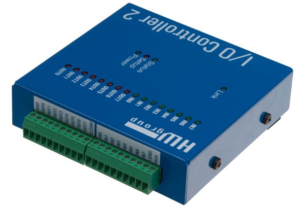
This code runs on a PIC 16F627A or 628A (and A.F.A.I.K 627/628 parts). It uses the serial USART on the PIC to communicate with a PC. Through this a simple CLI (Command Line Interface) is implemented that allows commands to be sent to the PIC to control output lines and read and return the status of inputs on the PIC
The serial interface is configured to operate at 9600bps, 8bits, No Parity, 1 stop bit.
Port A is configured as the output port, not forgetting that RA4 is an ‘input only’. Port B is used as the input port, again RB1 and RB2 are used by the PIC USART so aren’t available. In addition I have reserved RB0 for a Dallas 1-wire interface. Although the code isn’t implemented here, the RB0 port along with RB1 and RB2 is masked from the input status command so bits RB2,1,0 always return 0.
To summarise;
Outputs are RA0-3, RA5-7
Inputs are RB3-7
The CLI commands and functions are described below:
;
; Code displays the following message after a reset
; ‘PIC Serial IO controller ready’
; A ‘#’ is used as the command prompt.
; A ‘?’ is sent to the terminal when any command is either not
; recognised, or contains invalid or insufficient arguments.
;
; Commands (All commands are lowercase except the Restart command)
;
; v – display firmware version
; i – display value on input port
; o – display value of outputReg variable (see below)
; nx – set output bit x
; fx – clear output bit x
; tx – toggle output bit x
; where x is in the range 1 to 8 or 0 to operate on all bits simultaneously
; sxxxxxxxx/ – set output to bit pattern specified by xxxxxxxx mask
; where x must be 0 or 1. MSB is leftmost.
; All 8 bits must be specified and must terminate with ‘/’
;
; c – Continuous monitor and display of the input port
; . – Stop continuous monitor of the input port and return to command prompt
;
; m[io] – Toggle port value display format [ i = input, o = output ]
; displays port value as hex ‘HH’ or binary ‘bbbbbbbb’ MSB leftmost
; At startup the format will be hex.
;
; p[io] – Toggles between displaying the port status only, or printing a text string
; followed by the port status.
; e.g. with text “Input status : A5”, without “A5”
; At startup print mode will be port status only, no preceding text.
;
; w[ed] – Enable or Disable the weak pull-up feature on Port B
; Weak Pull Up is disabled at startup.
;
; R – Do a software restart (note: Uppercase R)
;
;
; Note: All output commands work on the outputReg memory variable.
; This is copied to the output port register on completion of each command.
; The show output port command does not read the port register, it reads
; and displays the value in the outputReg memory variable.
Screen dump of a sample terminal session
- Source Code (ZIP archive)
- Hex (right-click Save As) for 16F627A (also tested with 16F628A)
Notes:
- There are no schematics for this since it’s designed as a building block. You will need to interface pins RB1 and RB2 to a serial interface. RB1 is RXD input and RB2 is TXD output. The code configures the PIC to use the internal 4Mhz oscillator so no external crystal is needed.
For more detail: IO Controller with serial port CLI using PIC16F627A

