
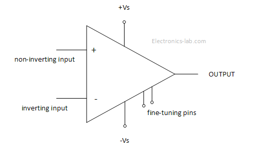
Operational amplifiers (OPAMPs) are high performance differential amplifiers in integrated form that can be used in many different ways. A typical OPAMP has a non-inverting input, an inverting input, two dc power pins, one output pin and a few other fine-tuning pins. On the following image you can see a typical diagram of an operational amplifier.
The basic OPAMP operation is simple. If the voltage applied to the inverting input is greater than the voltage applied to the non-inverting input then the output saturates to the negative supply voltage. In addition, if the voltage applied to the non-inverting input is greater than the voltage applied to the inverting input, then the output saturates at positive supply voltage.
This operation mode is limited and doesn’t give us the full idea behind OPAMP operation. The trick to make an OPAMP more useful is to provide negative feedback from the output to the inverting input. In the image below we see an OPAMP with negative feedback working as an inverting amplifier.
In this configuration a part of the output voltage is fed back to the inverting input and thus the gain of the OPAMP can be controlled and output isn’t saturating. The gain of such an amplifier is controlled by the two resistors Rf and Rin. The minus means that the output is inverted relative to input.
By adding more components on the feedback loop, different OPAMP circuits can be made, such voltage regulator circuits, current to voltage converters, oscillators, filters etc.
Beside the negative feedback, a positive feedback can be used. This way the OPAMP is driven toward saturation and works in either +Vs or –Vs output range. Applications of positive feedback is on comparator circuits and oscillators.
Theory
The basic formula that gives the output voltage in respect to input voltages is as follows. This formula tells that the output voltage is a function of the input voltages difference and of the open-loop voltage gain A0.![]()
This expression is for the ideal OPAMP and can get more complex for the real OPAMPs. Some rules apply to better understand the ideal and real OPAMPs.
- Rule 1: For the ideal OPAMP the open-loop voltage gain is infinite but for real OPAMP is in the range of to .
- Rule 2: For the ideal OPAMP the input impedance is infinite but for real OPAMPs is in the range to Ω. The output impedance of an ideal OPAMP is zero but for a real OPAMP is in the range 10 to 1000 Ω.
- Rule 3: The input terminals of an ideal OPAMP doesn’t draw any current and typically the same happens for the real OPAMP as the input current is very small.
- Rule 4: This rule applies to OPAMPS having negative feedback and tells us that when a voltage difference exists on the inverting and non-inverting input, the output increases in that direction so that the voltage fed back will keep that difference to zero.
For more detail: Introduction to OPAMPs and Applications
