Summary of Interfacing Stepper Motor with PIC Microcontroller
This article explains the operation of unipolar and bipolar stepper motors when interfaced with a PIC 16F877A microcontroller. It details three stepping modes for unipolar motors, emphasizing Wave Drive's low torque and power efficiency. The text distinguishes bipolar motors by their two-coil construction requiring an H-Bridge (L293D) for current reversal. Furthermore, it compares driver ICs L293D and ULN2003, highlighting their capabilities in driving inductive loads like motors and relays while protecting against back EMF through internal diodes.
Parts used in Stepper Motor Control Project:
- PIC 16F877A Microcontroller
- L293D H-Bridge Motor Driver
- ULN2003 Darlington Transistor Array
- Unipolar Stepper Motor
- Bipolar Stepper Motor
Introduction
A Stepper Motor is a brushless, synchronous DC electric motor, which divides the full rotation into a number of equal steps. It finds great application in field of microcontrollers such as robotics. Please refer the article Stepper Motor or Step Motor for detailed information about working of stepper motor, types and modes of operation. Unipolar Motor is the most popular stepper motor among electronics hobbyist because of its ease of operation and availability. Here I explaining the working of Unipolar and Bipolar Stepper Motor with PIC 16F877A Microcontroller.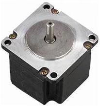
Microcontroller by using readymade ICs such as L293D or ULN2003. As I said in the article Stepper Motor or Step Motor, we have three different types of stepping modes for unipolar stepper motor.
Note: 1 – Represents Supply Voltage and 0 – Represents Ground
Wave Drive
In this mode only one stator electromagnet is energised at a time. It has the same number of steps as the full step drive but the torque is significantly less. It is rarely used. It can be used where power consumption is more important than torque.
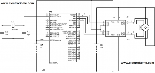
Driving Bipolar Motor
Bipolar motors are simpler in construction as it contains two coil and no centre tap. Being simple, driving is little complex compared to unipolar motors. To reverse the magnetic polarity of stator windings, current through it must be reversed. For this we should use H-Bridge. Here I using L293d, H-Bridge Motor Driver for that. We can distinguish bipolar motors from unipolar motors by measuring the coil resistance. In bipolar motors we can find two wires with equal resistance.
Interfacing Unipolar Stepper Motor with PIC Microcontroller
L293D and L293 are dual H-bridge motor drivers. The L293D can provide bidirectional drive currents of up to 600-mA at voltages from 4.5 V to 36 V while L293 can provide up to 1A at same voltages. Both ICs are designed to drive inductive loads such as dc motors, bipolar stepping motors, relays and solenoids as well as other high-current or high-voltage loads in positive-supply applications. All inputs of these ICs are TTL compatible and output clamp diodes for inductive transient suppression are also provided internally. These diodes protect our circuit from the Back EMF of DC Motor. In both ICs drivers are enabled in pairs, with drivers 1 and 2 are enabled by a high input to 1,2EN and drivers 3 and 4 are enabled by a high input to 3,4EN. When drivers are enabled, their outputs will be active and in phase with their inputs. When drivers are disabled, their outputs will be off and will be in the high-impedance state.
ULN2003 is a monolithic high current and high voltage Darlington transistor arrays. ULN2003 consists of seven NPN Darlington Transistor pairs that have high-voltage outputs with common-cathode clamp diode for switching inductive loads. The collector-current rating of a single darlington pair can be up to 500mA. We can connect Darlington Transistor pairs in parallel if higher current capability is needed..
Interfacing using L293D
For more detail: Interfacing Stepper Motor with PIC Microcontroller
- What is a Stepper Motor?
A brushless, synchronous DC electric motor that divides full rotation into equal steps. - Which stepper motor is most popular among electronics hobbyists?
The Unipolar Motor is the most popular due to its ease of operation and availability. - How does Wave Drive mode operate?
Only one stator electromagnet is energized at a time, resulting in significantly less torque but lower power consumption. - Why is driving a bipolar motor more complex than a unipolar motor?
Bipolar motors require reversing current through the windings to change magnetic polarity, necessitating an H-Bridge. - How can you distinguish a bipolar motor from a unipolar motor?
You can measure coil resistance; bipolar motors have two wires with equal resistance. - What is the function of the L293D IC?
The L293D is a dual H-bridge motor driver capable of providing bidirectional drive currents up to 600-mA for inductive loads. - What components are inside the ULN2003 array?
The ULN2003 consists of seven NPN Darlington Transistor pairs with high-voltage outputs and common-cathode clamp diodes.