Summary of Interfacing Relay with PIC Microcontroller
This article explains how to interface a relay with a PIC microcontroller to control high-voltage home appliances like a 230V AC bulb. It details the relay's working principle, involving NC, NO, and Common pins activated by an electromagnetic coil. The project utilizes a driver circuit comprising a transistor, resistor, diode, and power supply to safely manage voltage levels between the microcontroller and the relay.
Parts used in the Interfacing Relay with PIC Microcontroller:
- PIC Microcontroller
- 6V Relay
- 12V Power Supply
- Transistor BC547
- Resistor 1K
- Diode 1N4148WS
- 230 Volt AC Bulb
To control our high voltage device like home appliance by pic microcontroller, we have to have clear idea on interfacing relay with pic microcontroller. Here I try to answer your very important question with simulation that how to interface relay with pic microcontroller?
To discuss it elaborately I have to discuss what is relay? How it work? And how we can use it in our project?
Relay is an electrically operated switch work on electro-magnetism principal here you see the block diagram of relay. Here you see three pin named NC, NO and COMMON. Now NC stands for normally closed, NO for normally open and common stands for common pin for connecting NC or NO. P1 and P2 pin are for providing control signal to relay.
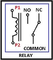
Now working principle of relay is very simple when P1 and p2 get a certain amount of voltage then coil between P1 and P2 get energized and create a magnetic field around it. For this magnetic field the metal switch liver which is attach to the common pin is attracted towards the NO pin and connection made between NO and common pin.
So by using relay switch we easily turn on or off any high voltage device by microcontroller. See the block diagram below to how we turn on or off a 230 volt AC bulb by micro controller.
Interfacing Relay with PIC Microcontroller :
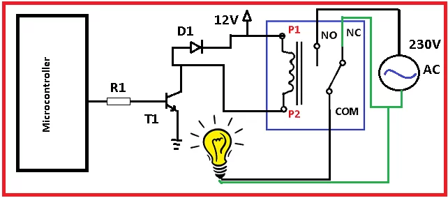
To interface relay with microcontroller we need a driver circuit to drive the power to relay. See the block diagram of driver circuit which I used in my project. Here I used diode D1(1N4148WS), Resistor R1 (1K), Transistor T1 ( BC547), 12 v power supply and 6V relay.
Now question is how the driver circuit works?
In my project I used 6V relay but supply given 12 V and diode D1 isolate the voltage between P1 and P2 pin. When microcontroller send out put voltage through R1 register at base of transistor T1, transistor T1 pull the some voltage through coil between P1 and P2 pin and grounded. Finally 6 volt is reached between pin P1 and P2 and relay is activated and it connect NO pin from NC pin of relay. When NO pin connected then bulb get 230 V ac and it glowing after some time delay it again off and repeating the step.
For more detail: Interfacing Relay with PIC Microcontroller
- How do you interface a relay with a PIC microcontroller?
You need a driver circuit consisting of a transistor, resistor, diode, and power supply to drive the power to the relay. - What is the function of the NC pin on a relay?
NC stands for normally closed and is one of the three pins used for connecting the common pin when the relay is inactive. - How does the relay switch work?
When P1 and P2 receive voltage, the coil creates a magnetic field that attracts a metal switch lever to connect the NO and common pins. - Why is a driver circuit necessary for this project?
A driver circuit is required to drive the power to the relay and isolate the voltage between the microcontroller and the relay coil. - What components are used in the driver circuit described?
The circuit uses diode D1 (1N4148WS), Resistor R1 (1K), Transistor T1 (BC547), a 12V power supply, and a 6V relay. - How is the 6V relay activated with a 12V supply?
The diode isolates the voltage so that when the transistor grounds the coil, 6 volts reach between pins P1 and P2 to activate the relay. - Can a microcontroller directly control a 230V AC bulb?
No, you must use a relay switch to easily turn on or off any high voltage device by the microcontroller. - What happens when the NO pin connects to the common pin?
The bulb receives 230V AC and begins glowing after a time delay before the cycle repeats to turn it off.