Summary of Interfacing Real Time Clock (RTC) DS1307 with PIC Microcontroller
The DS1307 is a low-power serial real-time clock featuring BCD timekeeping, 56 bytes of NV SRAM, and automatic leap year compensation. It communicates via a bidirectional I2C bus using an external 32.768kHz crystal oscillator without needing extra resistors or capacitors for operation. The chip includes power fail sensing to switch to backup supply automatically.
Parts used in the DS1307 RTC Project:
- DS1307 Real Time Clock
- 32.768kHz Crystal Oscillator
- Pull Up Resistors (1.8K recommended)
- I2C Bus (SCL and SDA lines)
- Ground Reference Line
- 5V Power Supply
- MikroC PRO for PIC Microcontroller Libraries
DS1307 is a low power serial real time clock with full binary coded decimal (BCD) clock/calendar plus 56 bytes of NV SRAM (Non Volatile Static Random Access Memory). Data and Address are transferred serially through a bidirectional I2C bus. The RTC provides year, month, date, hour, minute and second information. The end date of months is automatically adjusted for months fewer than 31 days including leap year compensation up to year 2100. It can operate either in 24-hour format or 12-hour format with AM/PM indicator. DS1307 comes with built-in power sensing circuit which senses power failures and automatically switches to back up supply. The DS1307 RTC uses an external 32.768kHz Crystal Oscillator and it does not requires any external resistors or capacitors to operate.
What is I2C (I²C) ?
I²C (Read as “i-squared cee”; Inter-Integrated Circuit) is a multi-master serial single-ended computer bus invented by Philips, used to attach low-speed peripherals to a embedded system,cellphone, motherboard, or other electronic device and is generally referred to as “two-wire interface”. It consists of two wires called SCL and SDA. SCL is the clock line which is used to synchronise all the data transfers through I2C bus and SDA is the data line. It also need a third line as reference line (ground or 0 volt). A 5v power should be also be given to the device for its working. The main thing to be noted is that both SCL and SDA are Open Drain drives. Which means that the chip can drive its low output but can’t drive high output. Thus we must provide two pull up resistors to 5v for SCL and SDA, to make it to drive high output as shown in the fig.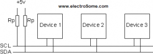
Selection of Pull Up Resistors
1. The rise time of SCL and SDA voltages will depend up on the value of pull up resistor and I2C bus capacitance. Thus pull up resistor should be selected according to the I2C bus frequency being used.
2. The higher value of pull up resistor is limited by the rise time and the lower vale of pull up resistor is limited by the drive strength (IOL max) of the SDA and SCL drivers. If the pull up resistor is very low , the SCL and SDA outputs might not be establish enough low voltage.
I recommend you to use 1.8K pull up resistors.
MikroC PRO for PIC Microcontroller provide built-in libraries for I2C devices. DS1307 works as a slave device on I2C bus. Register access can be obtained by implementing a START and followed by device identification address. Then each registers can be accessed sequentially by using its address until a STOP condition is executed.
Device Address : 0X68 = 1101000
For more detail: Interfacing Real Time Clock (RTC) DS1307 with PIC Microcontroller
- What components are required for the DS1307 to operate?
The project requires a DS1307 RTC, an external 32.768kHz crystal oscillator, pull-up resistors, SCL and SDA lines, a ground reference, and a 5V power supply. - How does the DS1307 handle power failures?
The device has a built-in power sensing circuit that automatically switches to the backup supply when a power failure is detected. - Can the DS1307 operate with external resistors or capacitors?
No, the DS1307 does not require any external resistors or capacitors to operate besides the necessary pull-up resistors for the I2C bus. - What is the function of the SCL line in the I2C bus?
The SCL line serves as the clock line used to synchronize all data transfers through the I2C bus. - Why are pull-up resistors needed for SCL and SDA?
Since SCL and SDA are Open Drain drives, pull-up resistors must be provided to allow the chips to drive high output levels. - What pull-up resistor value is recommended for this project?
The article recommends using 1.8K pull-up resistors for optimal performance. - Does the DS1307 support both 12-hour and 24-hour formats?
Yes, the DS1307 can operate in either 24-hour format or 12-hour format with an AM/PM indicator. - How is data transferred between the microcontroller and the DS1307?
Data and address are transferred serially through a bidirectional I2C bus using START, device identification, sequential register access, and STOP conditions.