
Summary of Aurora 48 – 48 RGB LED Sequencer using PIC24FV16KA304
Aurora 48 is a compact, thin-profile full-color LED sequencer designed for wearable projects. It features a clean surface-mount construction capable of individually controlling 48 RGB LEDs with smooth gamma-corrected fades and 11 pre-programmed patterns. The device utilizes a PIC24FV16KA304 microcontroller and a binary decoder to manage multiplexing via a simple one-button interface, allowing for easy firmware upgrades.
Parts used in the Aurora 48:
- 24x 68 ohm (0603) resistors
- 6x 220 ohm (0603) resistors
- 6x 1k ohm (0603) resistors
- 2x 10k ohm (0603) resistors
- 4x 0.1uF capacitors (0603)
- 2x 10uF capacitors (1206)
- 6x MMBT2222A transistors
- 1x PIC24FV16KA304 microcontroller
- 1x 74HC238 binary decoder IC
- 48x PLCC4 RGB LEDs (common-anode)
- 1x Tactile Switch
Aurora 48 is a compact and thin profile full-color LED sequencer. It’s built entirely with surface mount components, so the profile is nice and clean.
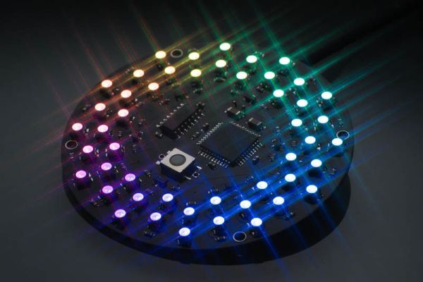
Features
- Capable of individually controlling 48 Full color LEDs.
- Each LED can be faded in 7 bit per channel – 2,097,152 colors.
- Gamma corrected brightness curve for very smooth fades.
- Simple, one button control.
- 11 sequence pattern (as of firmware version 1.0).
- Compact – 2.68 inch (68 mm) in diameter.
- Thin profile construction (0.137 inch (3.5 mm) thick).
- No leads sticking out on the back. Ideal for wearable projects.
- Firmware is easily upgradable via 5 pin ICSP connection.
Circuit
Aurora 48 is capable of individually controlling 48 Full color LEDs using a 40 pin microcontroller. The principle of operation is based on my other “Aurora”s. (see Aurora 9×18)
 The circuit is relatively simple and straightforward. If you’ve seen other LED matrix type circuit, this should look familier.In a nutshell, the 48 RGB LEDs are divided in two groups, connected in a 6:1 multiplex fashion, taking R, G, and B as bus lines, and common pin of each LED as column lines. There are two pairs of R/G/B buses. Since there are only 3 PWM outputs available on the controller used, I used a binary decoder IC to multiplex the PWM signal, to drive 6 bus lines. 3 pins are used to select one of the 6 buses, and 24 pins are used to control LEDs’ common pins.The controller activates one bus at a time, outputs a pulse to the LED that should be lit. The actual duration that a particular LED turns on is controlled by the PWM pulse that goes into the binary decoder, 74HC238. The controller sends PWM pulses as short as 62.5 ns to as long as 12,500 ns to control the brightness.
Parts & PCB
Here’s the part list.
- 24x 68 ohm (0603) (RC1-24)
- 6x 220 ohm (0603) (R1,3,5,7,9,11)
- 6x 1k ohm (0603) (R2,4,6,8,10,12)
- 2x 10k ohm (0603) (R13,14)
- 4x 0.1uF (0603)
- 2x 10uF (1206)
- 6x MMBT2222A
- 1x PIC24FV16KA304
- 1x 74HC238
- 48x PLCC4 RGB LED (common-anode)
- 1x Tactile Switch
Assembly
Assembly is very much straightforward, that is if you are familier with surface mount soldering. Please don’t be discouraged – surface mount soldering is not difficult and can be done without special equipment. There are many instructables and YouTube how-to videos showing how to solder SMDs. With a little practice you can solder SMD very easily.Since the PCB doesn’t have silkscreen indicating the parts, use the part placement guide provided to locate the spots for the parts.Start with the center of the PCB and move outwards – 74HC238 and PIC24FV16KA304 would be the first ones to solder. Be sure to apply good amount of flux to the parts to be soldered. Move on to resistors, capacitors, transistors.
for more info visit: Aurora 48 – 48 RGB LED Sequencer using PIC24FV16KA304
-
How many colors can each LED display?
Each LED can be faded into 2,097,152 colors using 7 bits per channel. -
Can the firmware be upgraded on the Aurora 48?
Yes, the firmware is easily upgradable via a 5 pin ICSP connection. -
What is the best way to start soldering the components?
Start with the center of the PCB by soldering the 74HC238 and PIC24FV16KA304 first, then move outwards. -
Does the device have leads sticking out on the back?
No, there are no leads sticking out on the back, making it ideal for wearable projects. -
How does the circuit control the brightness of the LEDs?
The controller sends PWM pulses ranging from 62.5 ns to 12,500 ns to control brightness. -
What is the diameter of the Aurora 48 board?
The board has a compact diameter of 2.68 inches (68 mm). -
How are the 48 RGB LEDs divided in the circuit?
The LEDs are divided into two groups connected in a 6:1 multiplex fashion.
