Summary of Hee Haw Sound
This article describes an experiment that generates a Hee Haw alarm sound using nested loops on a PIC16F84 microcontroller, swapping timing values between HEE and HAW sections so both last equal durations. It includes assembly code for toggling a piezo output with adjustable high/low durations and cycle counts. A second experiment outlines a simple A-to-D conversion concept using a capacitor and resistor to measure analogue voltages with digital lines. The source provides annotated code and a brief explanation of implementing analogue input without an internal ADC.
Parts used in the Hee Haw Sound:
- PIC16F84 microcontroller
- Piezo buzzer
- 10k potentiometer (mentioned in A to D experiment)
- Capacitor (for A to D conversion)
- Resistor or unknown resistor/device under test (for A to D conversion)
- Power supply (5V implied)
- Connecting wires and breadboard or PCB
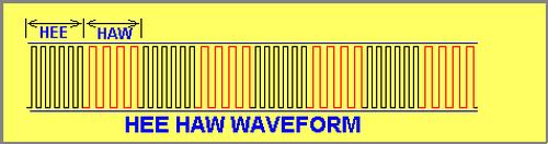
This experiment creates a Hee Haw sound for an alarm. The diagram shows the number of cycles for the HEE and the time taken for each cycle, equates to a certain length of time. The frequency of the HAW is lower and the number of cycles must be worked out so that the time for the HAW is equal to the time for the HEE.
This is simple when writing the program. The values loaded into the two files for the HEE are reversed for the HAW.
The routine consists of two sections: HEE and HAW. Each section has two nested loops. The inner loop creates the length of time for the HIGH and LOW to produce a single cycle and the outer loop creates the number of cycles.
| ;Expt7a.asm ;Project: Hee Haw Sound List P = 16F84 #include <p16F84.inc> __CONFIG 1Bh ;_CP_OFF & _PWRTE_ON & _WDT_OFF & _RC_OSC |
||
SetUpHee1 Hee2 Hee3 Hee4 Haw1 Haw2 Haw3
|
ORG 0 BSF 03,5 CLRF 06 BCF 03,5 CLRF 06 GOTO Hee1MOVLW 0FFh MOVWF 14h MOVLW 0C0h BSF 06,7 NOP DECFSZ 15h,1 GOTO Hee3 MOVLW 0C0h MOVWF 15h BCF 06,7 NOP DECFSZ 15h,1 GOTO Hee4 DECFSZ 14h,1 GOTO Hee2 MOVLW 0C0h END |
;This is the start of memory for the program. ;Go to Bank 1 ;Make all port B output ;Go to Bank 0 – the program memory area. ;Clear display;Number of loops ;The loop file ;Duration of HIGH ;Turn on piezo ;Create the HIGH time ;Duration of the LOW ;Create the LOW time ;Decrement the loop file ;Number of loops ;Turn on piezo ;Create the HIGH time ;Duration of the LOW ;Create the LOW time ;Decrement the loop file |
EXPERIMENT 8
A to D Conversion
This experiment shows 0-256 parts of a 10k potentiometer on the 8 LEDs. It is not accurate, but shows the concept of A to D conversion.
Many microcontrollers have an input that can read any value of voltage from 0v to 5v (and higher by using a voltage divider network). Normally there are 256 steps in this range to produce a resolution of approx 20mV for 0-5v scale. This is called an A to D input (A to D converter – analogue input) and is ideal for measuring voltages and other values that are classified as ANALOGUE. A very simple external circuit can be added to measure different parameters such as the change in resistance of a temperature probe and other analogue devices.
The PIC16F84 does not have an internal A to D converter, however we can create an A to D feature by using two lines and a sub-routine.
To create an analogue input, a capacitor “C” is connected in series with an unknown resistor (R) and charged via one of the lines of the microcontroller. The diagram below shows how this is done.
For more detail: Hee Haw Sound
- How is the Hee Haw sound produced on the PIC16F84?
By two routine sections named HEE and HAW, each with nested loops: inner loops set HIGH and LOW durations, outer loops set number of cycles, toggling a piezo output. - Can the HEE and HAW durations be made equal?
Yes; the frequency of HAW is lower so the number of cycles for HAW is calculated so its total time equals HEE, implemented by reversing values loaded into the two files. - What does the inner loop in each section do?
The inner loop creates the length of time for the HIGH and LOW to produce a single cycle. - What does the outer loop in each section do?
The outer loop creates the number of cycles. - Does the PIC16F84 have a built-in A to D converter?
No, the PIC16F84 does not have an internal A to D converter; a simple external method with a capacitor and resistor is used instead. - How is an analogue input simulated without an ADC?
By connecting a capacitor in series with an unknown resistor, charging it via a microcontroller line, and using timing to infer voltage across 0-5V range. - What resolution is typical for a 0-5V A to D scale described?
The article states 256 steps giving approx 20mV resolution for a 0-5V scale. - What components are needed for the A to D demonstration?
A capacitor, an unknown resistor or sensor, and microcontroller lines to charge and measure timing; a potentiometer is shown for 0-256 parts demonstration on LEDs.