Summary of HC08 Fan Timer using pic microcontroller
This article details a DIY fan timer project replacing a broken mechanical unit using a Motorola Nitron MC68HC908QY4 microcontroller. The design eliminates passive components by utilizing C code compiled with ICC08 for timing logic. It includes a loader schematic featuring a MAX232 interface and an external 9.8304MHz oscillator, alongside a zero-power standby circuit that latches via a relay. The software reads a potentiometer to set durations up to five hours, controlling the relay output through PTA3.
Parts used in the HC08 Fan Timer:
- Motorola Nitron MC68HC908QY4 (16-pin PDIP)
- MAX232 chip
- 74HC04 CMOS inverter
- 9.8304MHz crystal oscillator
- 10k POT B type (R6)
- NPN transistor
- 12V electromechanical relay
- D2 diode (for back EMF protection)
- C3 multilayer 0.1uF decoupling capacitor
- S1 push button
Build a timer with Motorola Nitron MCU and using ICC08 to develop c program. Loader schematic also included. New s-record for 8-pin 68HC908QT2!
My son got his fan in the bedroom. The fan has mechanical timer for 0-180mins. One day it broken. So I got the idea to use Nitron chip to replace the mechanical timer. Someone may ask me why so complicated timer made by microcontroller chip? Actually we can build a timer with 555 and a 14-stage cmos counter! The 555 runs astable with time constant controlled by RC and for long period timing we can divide the output frequency of 555 by a cmos counter. That was my homebuilt timer 20 Yrs ago. Such circuit needs a number of passive components. We will see the hardware for timer with Motorola Nitron chip, it is only 16-pin MCU and one decoupling cap. All passive components and timing function are replaced with c coding
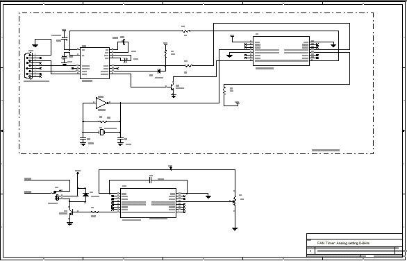
 Hardware Schematic
The loader circuit is shown in the block. The hardware settings (external clock with high voltage) forces Nitron chip to run in monitor mode. The IRQ(PTA2) ties to pin 2 of MAX232 to provide HV signal. The external oscillator is required for 9600 BAUD send/receive monitor command via PTA0. It made with CMOS inverter 74HC04 and xtal 9.8304MHz. PTA1 and PTA4 also are required. The free software loader, PROG08SZ V1.7 can get from http://www.pemicro.com/.
The HC08 Fan timer circuit is shown below the loader. The Nitron chip is MC68HC908QY4, 16pin PDIP. When using the ICC08 program, you can choose the programming algorithm with QY4, say. R6 is 10k POT B type tied to the AD0, analog input channel0. It used to set time from 0Hr to 5Hrs. The output relay driving circuit is PTA3. A small NPN transistor drives a 12V electromechanical relay. D2 provides a path for back EMF current flowing when Q2 is turned off. C3 is multilayer 0.1uF decoupling cap. The Nitron chip has internal clock, power reset, low voltage detection, watchdog. You may learn more features from Niron Data sheet.
Zero Power Standby
Figure 2 shows a sample schematic featuring zero power standby. By using a push button S1 to make K1’s contact closed when S1 was pressed. The K1’s contact will close and latch with period setting by R6. When time-out the K1’s contact will open thus turns itself power off. To restart timer, just press S1 again.
Software
As shown in the schematic, we see that the timer circuit has only one 16-pin MCU, so all timing functions are done by program.
| /* timer.c firmware for cheap timer using Nitron chip MC908QY4CP 16-pin MCU compiled with icc08 Time setting is made by 10k POT, the analog input 0-5V. Time(mins) = (ADC reading *300)/255 Copyright (c) 2004 Wichit Sirichote, [email protected] */ #define minute 7200// 120 ticks = 1 sec, so 7200 ticks = 1 minute char count;char n,timer1;unsigned int timer2,timer3;unsigned char sec;unsigned int min, PV, save_time,set_time;char x1,x2,x3;char minute_pass;void disable_timer(){ if(set_time <5) PTA &= ~0x8; // off timer}void minute_clock(){ timer2++; if (timer2 > minute) {timer2 = 0; minute_pass = 1; }}void run_timer(){ if (timer3 > 10) { PTA |= 0x8;// output high relay if (minute_pass == 1) { minute_pass = 0; |
For more detail: HC08 Fan Timer
- How is the timer time setting adjusted?
The time is set from 0 to 5 hours using a 10k POT B type tied to analog input channel 0. - Can the Nitron chip replace a mechanical timer?
Yes, the Nitron chip replaces the mechanical timer to control a bedroom fan with programmable duration. - What software is used to compile the program?
The C program is developed and compiled using the ICC08 compiler. - Does the circuit require many passive components?
No, all timing functions are replaced with C coding, requiring only one MCU and a decoupling cap. - How does the zero power standby feature work?
A push button closes a contact to latch the relay; when the time-out occurs, the contact opens to cut power. - What frequency is used for the external oscillator?
The external oscillator uses a 9.8304MHz crystal made with a CMOS inverter 74HC04. - Which pin controls the output relay?
The output relay driving circuit is connected to PTA3 on the Nitron chip. - How is the high voltage signal provided for the loader?
The IRQ(PTA2) ties to pin 2 of MAX232 to provide the HV signal required for monitor mode. - What free software can be used to load the program?
The free software loader PROG08SZ V1.7 can be downloaded from pemicro.com.