Summary of GPS REPEATER/SYSTEMS MONITOR using PIC16F876
This article describes a GPS data repeater circuit using a PIC16F876 microcontroller, designed to display GPS and boat system data on an LCD. It connects to Garmin-38 receivers, accepting NMEA-0183 input via a DB-9 jack and serial UART. The device features three display pages (Position, Waypoint, Battery), analog voltage monitoring, and configurable crystal speeds and display sizes.
Parts used in the GPS Repeater:
- PIC16F876 Microcontroller
- LCD Display (16x4 or 20x4)
- DB-9 Jack
- Three Push Buttons
- Crystal Oscillator (4MHz to 20MHz)
- GPS Receiver (Garmin-38 compatible)
- Analog Voltage Inputs (3 channels)
Introduction
This circuit is a repeater for GPS data. It is intended to connect to Garmin-38 (and similar) hand held GPS receivers that don’t have external antennas. The purpose for the repeater is to allow the GPS to be outside, exposed to the satellite view, and allow the user to see the data below decks at the navigation station.
Versions
Within the code there is opportunity to easily configure for a 16×4 display or a 20×4 display, as well as configure it for crystal speeds from 4 to 20MHz, and for nautical, metric, or statute speed display. Although the description below is for the 16×4 version, the 20×4 is quite similar.
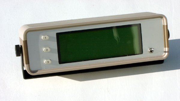
Herb Young in Australia built a very nice boxed version of the repeater.
Features
The repeater displays several pages of data pertaining to both the GPS and the boat electrical system. A DB-9 jack is on the front panel for the purposes of connection of a laptop to upload and download GPS waypoint data, etc. This code is a good example of how to process serial data using the PIC16F87x hardware UART and the serial interrupt.
Specifications
- Power: 10-16VDC at ~150mA including GPS
- Analog: three inputs, 14.99VDC maximum displayed value
- Data: NMEA-0183 2.0 format (4800 baud, TTL level, RMB & RMC data sentences)
Operation
Apply power to the repeater. The following screen is displayed
- The three buttons cycle through the three pages, which are:
- Position (Latitude – Longitude – Speed – Heading)
- Waypoint (Waypoint name – Steering – Distance – Bearing)
- Battery voltages
- Pressing and holding the Position button for between one and three seconds toggles the background illumination on and off.
- Pressing and holding the Position button for four or more seconds resets the microprocessor (like power-on-reset.)
- Pressing and holding the Position button during power-up will display the Setup Page, described below.
Code:
// Change the following to change the clock frequency
#define CRYSTAL_FREQ    16000000
// Change the following to change between 16 or 20 column display
#define DISPLAY_COLS    20
// Speed units are "1" (nautical knots), "2" (metric kph), or "3" (statute mph)
#define SPEED_UNITS     1

/****************************************************************************
GPS18.c

This program receives NMEA-0183 data from a GPS and displays it.
Meant for large display version still in 16F876.
Three buttons
Automicaly resets if main loop stops (not the best solution, still don't know why it's stopping)

Next: don't display GPS screens unless GPS is active
      detect display needing reset
      preset data eeprom for first-time operation
      don't display init stuff if reseting from main loop

                 +5                       +5+5
                  |                        | |
                  20                      15 2
                ----------             ----------
~SerIn -----18-|          |-24-----11-|DB4 A Vdd |
               |          |-25-----12-|DB5       |
  ADC0 ------2-|          |-26-----13-|DB6       |
  ADC1 ------3-|  16F876  |-27-----14-|DB7     Vo| 3--
  ADC2 ------5-|          |           |    LCD   |    |
               |          |-14------6-|EN        |    |
       XTAL--9-|          |-15------4-|R/S       |    |
       XTAL-10-|          |-28-FET-16-|K         |    |
               |          |           |  RW  Vss |    |
 BUTTON 1---21-|          |            ----------     |
 BUTTON 2---22-|          |              1   5        |
 BUTTON 3---23-|          |              |   |        |
               |          |             Gnd Gnd       |
               |          |                           |
               |          |-11----------R/C-----------
               |          |
               |          |
                ----------
                  8    19
                  |     |
                 Gnd   Gnd

***************************************************************************/
#case
#include < 16F876.h >
#include < jonsinc.h >
#device = *=16 ADC=10                /* allow RAM addresses over 255 */

#if ( ( CRYSTAL_FREQ < 4000000) || ( CRYSTAL_FREQ > 20000000 ) )
#error "CRYSTAL FREQ" not defined to between 8000000 and 20000000
#endif
#if ( ( DISPLAY_COLS != 16 ) && ( DISPLAY_COLS != 20 ) )
#error "DISPLAY COLS" not defined to 16 or 20
#endif

// RMC_TIME = 1 per clock megahertz, rounded
#define RMC_TIME        CRYSTAL_FREQ/1000000

#define LCD_D0          PIN_B3
#define LCD_D1          PIN_B4
#define LCD_D2          PIN_B5
#define LCD_D3          PIN_B6
#define LCD_EN          PIN_C3
#define LCD_RS          PIN_C4
#define RX_IN           PIN_C7
#define BUTTON_1        PIN_B0
#define BUTTON_2        PIN_B1
#define BUTTON_3        PIN_B2
#define LCD_BACKLITE    PIN_B7
#define LINE_1          0x00
#define LINE_2          0x40
#if DISPLAY_COLS == 20
#define LINE_3          0x14
#define LINE_4          0x54
#endif
#if DISPLAY_COLS == 16
#define LINE_3          0x10
#define LINE_4          0x50
#endif
#define CLEAR_DISP      0x01
#define EOF             0x00
#define COMMA           ','
#define CR              13
#define SPACE           ' '
#define PERIOD          '.'
#define DEGREE          0xdf
#define DOLLAR          '$'
#define NULL            0
#define GPRMC_CODE      75
#define GPRMB_CODE      74
#define RX_BUFFER_SIZE  70
#define POSITION_SCREEN 1
#define WAYPOINT_SCREEN 2
#define BATTERY_SCREEN  3
#define HIDDEN_RMC      5
#define WARNING_MSG     0
#define NODATA_MSG      1
#define ACTIVITY_SYMBOL 0xFF
#define MAX_VOLTS       15
#define EEPROM_CONTRAST 0
#define EEPROM_INITIAL  1

/* Set the following define to "YES" to display XOR'ed GPS sentence code */
/* such as GPRMC and the display will read out the value of 74. */
#define GET_GPS_CODE    NO

#separate void Display ( void );
#separate void LCD_Init ( void );
#separate void LCD_SetPosition ( unsigned int cX );
#separate void LCD_PutChar ( unsigned int cX );
#separate void LCD_PutCmd ( unsigned int cX );
#separate void LCD_PulseEnable ( void );
#separate void LCD_SetData ( unsigned int cX );
#separate void SkipField ( char cCnt );
#separate char GetField ( void );
#separate void InitRxBuffer ( char cCode );
#separate char GetRxChar ( void );
#separate void DisplayLatLon ( void );
#separate void DisplayWaypoint ( void );
#separate void DisplayLatitude ( char cLine );
#separate void DisplayLongitude ( char cLine );
#separate void DisplayHeading ( char cLine );
#separate void DisplaySpeed ( char cLine );
#separate void DisplaySteer ( char cLine, char cX );
#separate void DisplayWaypointName ( char cLine, char cX );
#separate void DisplayDistance ( char cLine, char cX );
#separate void DisplayBearing ( char cLine, char cX );
#separate void GetUtcAndMagVar ( void );
#separate long TrueToMag ( long iH );
#separate long FieldFiveToLong ( void );
#separate void DisplayAnalog ( void );
#separate void DisplayScaledVoltage ( long iV, char cScale );
#separate void DisplayArrival ( char cLine );
#separate void DisplayMessage ( char cMsgNum );
#separate void DisplayTemplateLatLon ( void );
#separate void DisplayTemplateWaypoint ( void );
#separate void DisplayTemplateAnalog ( void );
#separate void Delay5mS ( char cCnt );

#fuses HS, NOPROTECT, PUT, NOWDT, BROWNOUT, NOLVP, NOCPD
#use standard_io ( A )
#use standard_io ( B )
#use standard_io ( C )
#use delay ( clock = CRYSTAL_FREQ )
#use rs232 ( baud=4800, xmit=PIN_C6, rcv=PIN_C7, ERRORS )    // XMIT must be assigned to enable hardward USART
#priority RDA, RTCC, EXT

static char cC [ 10 ];      // local buffer
static char cTimeOut;
static char cRxBuffer [ RX_BUFFER_SIZE ];    // Fifo
static char cRxByteCnt;         // Number of bytes in the recv fifo
static char *cRxBufferWritePtr;    // Pointers for the Rx buffer
static char *cRxBufferReadPtr;
static char cRxIsrState, cRxMsgTypeReceived, cRxMsgTypeDesired;
static char cRxMsgReady, cReceiveFlag;
static long iVar, iLastRange, iTimeOut;
static char cVarDir, cScreenChanged, cAdcDone;
static char cButtonPressed, cSkip, cButtonCount;
static char cScreen, cSavedScreen, cRmcTimer1, cRmcTimer2;
static char cToFrom [ 5 ], cIndicator, cIllumination, cRxErrorFlag;
static char cDone, cContrast;

/*******************************************************************/
#int_ad
void AdcInterrupt ( void )
    {
    /* Gets here when ADC is done conversion, sets flag */
    cAdcDone = YES;
    }

#int_timer1
void Timer1Interrupt ( void )
    {
    /* Periodic RMC data timer, gets here every 204mS */
    /* This routine forces RMC to run every 10 minutes to update */
    /* magnetic variation */
    if ( cRmcTimer1-- == 0 )
        {
        cRmcTimer1 = 255;               // 52 seconds @ 10.240MHz
        if ( cRmcTimer2-- == 0 )
            {
            cRmcTimer2 = RMC_TIME;      // triggers every 10 minutes
            cSavedScreen = cScreen;     // save current screen type
            cScreen = HIDDEN_RMC;       // force RMC to run
            }
        }
    }

#int_rtcc
void Timer0Interrupt ( void )
    {
    // Gets here every 16.4mS at 8MHz, 8.2mS at 16MHz
    // Handles data timeout and switch debounce.

    // DATA TIMEOUT TIMER
    if ( cTimeOut != 0 )
        {
        cTimeOut--;
        }

    // This timer is preset by the normal operating loop, unless the operating
    // loop stops looping, at which point iTimeOut finally decrements to zero
    // and resets CPU.
    if ( iTimeOut != 0 )
        {
        iTimeOut--;
        }
    else
        {
        reset_cpu();                // force reset
        }

    if ( input ( BUTTON_2 ) == LOW )  // if button still pressed
        {
        cScreen = WAYPOINT_SCREEN;
        cSkip = YES;                // skip out of anything in process
        cScreenChanged = YES;       // repaint complete screen
        }

    if ( input ( BUTTON_3 ) == LOW )  // if button still pressed
        {
        cScreen = BATTERY_SCREEN;
        cSkip = YES;                // skip out of anything in process
        cScreenChanged = YES;       // repaint complete screen
        }

    // SWITCH DEBOUNCE
    if ( input ( BUTTON_1 ) == LOW )  // if button still pressed
        {
        if ( cButtonCount < 255 )   // hold at 255
            {
            cButtonCount++;         // otherwise increment
            }
        }
    else            // if button is unpressed
        {
        if ( cButtonCount > 2 )     // filter out glitches
            {
            //If button press is greater than 3.3 seconds, cold reset
            if ( cButtonCount == 255 )
                {
                reset_cpu();
                }
            if ( ( cButtonCount > 57 ) && ( cButtonCount < 255 ) )
                {
                if ( cScreen != HIDDEN_RMC )       // if not in the middle of getting magnetic variation
                    {
                    // cIllumination ^= ON;
                    output_bit ( LCD_BACKLITE, cIllumination ^= ON );
                    }
                }
            // If button press is less than 0.5 second
            if ( cButtonCount <= 57 )
                {
                if ( cScreen != HIDDEN_RMC )       // if not in the middle of getting magnetic variation
                    {
                    //if ( cScreen++ >= BATTERY_SCREEN )   // increment to next screen
                        {
                        cScreen = POSITION_SCREEN;                    // wrap
                        }
                    cSkip = YES;                // skip out of anything in process
                    cScreenChanged = YES;       // repaint complete screen
                    }
                }
            }
        cButtonCount = 0;       // restart
        }
    }

#int_rda
void SerialInterrupt ( void )
    {
    /*
    Reads incoming data from the USART and puts in in a rolling buffer
    ( but in this application, it should never roll.)
    If the buffer is full, this routine just discards the received byte.
    Not checking the LRC byte at the end of the NMEA-0183 sentence.
    */
    char cChar;

    if ( rs232_errors & 0x04 )  // get framing error bit from Rx status reg
        {
        cRxErrorFlag = ON;
        }
    cChar = getchar();       // get char from UART, clear any errors

    if ( cRxByteCnt == RX_BUFFER_SIZE ) // is recv fifo full ???
        {
        goto done;
        }
    switch ( cRxIsrState )
        {
        case 0:
            {
            if ( cChar == DOLLAR )  // if start of NMEA0183 message
                {
                cRxByteCnt = 0;     // reset byte count
                cReceiveFlag = OFF;     // default to off
                cRxMsgTypeReceived = NULL;  // set hashed value to null
                cRxIsrState++;                 // next state
                }
            break;
            }
        case 1:                           // five type characters to obtain
        case 2:
        case 3:
        case 4:
        case 5:
            {
            cRxMsgTypeReceived ^= cChar;      // hash in msg type
            if ( cRxIsrState++ == 5 )        // if time to check message type
                {
                if ( cRxMsgTypeReceived == cRxMsgTypeDesired )  // if good
                    {
                    cReceiveFlag = YES;            // enable receiving
                    cRxBufferWritePtr = cRxBuffer;    // reset to beginning of buffer
                    }
                else                    // don't want this message
                    {
                    cRxIsrState = 0;    // reset to look for next msg
                    }
                }
            break;
            }
        case 6:
            {
            /* Case 6 skips the comma character following msg type */
            cRxIsrState++;
            break;
            }
        default:                          // remainder of characters
            {
            if ( cReceiveFlag == YES )        // if this message is wanted
                {
                *cRxBufferWritePtr = cChar;     // put char in fifo
                cRxBufferWritePtr++;            // increment pointer
                if ( cRxBufferWritePtr == ( cRxBuffer + RX_BUFFER_SIZE ) ) // pointer past end ?
                    {
                    cRxBufferWritePtr = cRxBuffer;      // set pointer to start of fifo
                    }
                cRxByteCnt++;              // Increment byte count
                if ( cChar == CR )
                    {
                    cRxMsgReady = YES;         // signal that message is ready
                    cReceiveFlag = NO;      // no more receive
                    }
                }
            }
        }
    done:;
    }

/*******************************************************************/
For more detail: GPS REPEATER/SYSTEMS MONITOR using PIC16F876
- What is the primary purpose of this circuit?
The circuit acts as a GPS repeater to allow users to view satellite data below decks while the receiver remains outside. - How does the user switch between display pages?
Pressing one of the three buttons cycles through Position, Waypoint, and Battery voltage screens. - Can the display size be changed in the code?
Yes, the code allows configuration for either a 16x4 or a 20x4 display. - What happens if the Position button is held for four seconds?
Holding the button for four or more seconds resets the microprocessor similar to a power-on reset. - How can the background illumination be toggled?
Press and hold the Position button for one to three seconds to turn the backlight on or off. - Does the system support different speed units?
Yes, the code can be configured for nautical knots, metric kph, or statute mph. - What format does the GPS data use?
The system processes NMEA-0183 2.0 format data at 4800 baud with TTL levels. - How does the device handle a frozen main loop?
A watchdog timer detects if the main loop stops and automatically resets the CPU.