
Summary of Getting started with PIC18F Microcontrollers
Summary: This article introduces using the StartUSB for PIC development board with the PIC18F2550 to move from PIC16F to enhanced PIC18F series. It explains board features (USB bootloader, miniUSB, crystal, LEDs, prototyping pads), required software (mikroC Pro for PIC and mikroBootloader), and provides a first test Hello World program that blinks two onboard LEDs alternately every 500 ms.
Parts used in the StartUSB for PIC project:
- StartUSB for PIC development board (with PIC18F2550)
- PIC18F2550 microcontroller (onboard)
- miniUSB connector (onboard)
- 8.0 MHz crystal oscillator (onboard)
- Power indicator LED (onboard)
- Two additional user LEDs connected to RA1 and RB1 (onboard)
- Jumpers for LED connections (onboard)
- Prototyping pads/areas (onboard)
- mikroBootloader PC application (software)
- mikroC Pro for PIC compiler (software)

So what is StartUSB for PIC?
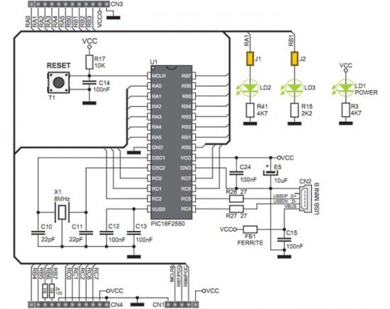
StartUSB for PIC is a small development board featuring PIC18F2550 microcontroller with fast USB 2.0 support. It features connection pads for all MCU pins, as well as two additional prototyping areas for placing additional components. The biggest advantage of this board is that the microcontroller comes preprogrammed with fast USB bootloader, and so there is no need of any external programmer. You can transfer your application related HEX file from PC to PIC’s program memory using mikroBootloader. MikroBootloader is the PC application developed by mikroElektronika for their USB HID Bootloader. On board miniUSB connector, oscillator (8.0 MHz crystal), reset circuit, power indicator LED, as well as two additional LEDs provide all you need for quick start. The two additional LEDs are connected to RA1 and RB1 pins of PIC18F2550 through jumpers. The picture above shows the StartUSB for PIC board with all the components and additional prototyping areas.
Today’s tutorial is important because we will discuss about a complete setup for StartUSB for PIC board that will let you start your journey into the world of PIC18F series microcontrollers. The first thing you need to install is mikroC Pro for PIC, which is a C compiler developed by mikroElektronika for PIC12, PIC16, and PIC18 series microcontrollers. You can download the demo version of this software that will allow you to compile programs up to 2 K of program words. Once you installed the compiler, download the mikroBootloader, which is PC’s application to communicate with the bootloader program stored inside the PIC18F2550 microcontroller on the StartUSB board.
Testing the board with “Hello World”
We will begin our journey with a simple test program that will make sure everything is setup correctly and we will be ready for doing more advanced experiments with PIC18F2550. This program will flash the two on-board LEDs (connected to RA1 and RB1 pins) alternately with 500 ms duration. In mikroC Pro for PIC, applications are developed in the form of projects. If you haven’t used mikroC Pro for PIC before, the document ‘Creating first project in mikroC Pro for PIC‘ from mikroElektronika will guide you to create your first project. While following those steps, select the microcontroller as PIC18F2550 and the device clock as 8.0 MHz. In the main program window, type in the following program.
 sbit LED1 at RA1_bit;
For more detail: Getting started with PIC18F Microcontrollers
- What is StartUSB for PIC?
StartUSB for PIC is a small development board featuring the PIC18F2550 microcontroller with fast USB 2.0 support, onboard bootloader, miniUSB connector, oscillator, LEDs, and prototyping areas. - Do I need an external programmer to program the PIC18F2550 on StartUSB for PIC?
No, the microcontroller comes preprogrammed with a fast USB bootloader so no external programmer is needed. - How do I transfer a HEX file to the StartUSB for PIC board?
You transfer the application HEX file from PC to PIC program memory using the mikroBootloader PC application. - Which compiler is recommended for developing applications for StartUSB for PIC?
mikroC Pro for PIC is recommended; it supports PIC12, PIC16, and PIC18 series. - What clock settings should I select when creating a project for PIC18F2550 in mikroC Pro for PIC?
Select microcontroller PIC18F2550 and device clock as 8.0 MHz (external crystal). - Which pins are the two on-board LEDs connected to?
The two additional LEDs are connected to RA1 and RB1 pins of PIC18F2550 through jumpers. - What does the provided Hello World test program do?
The test program flashes the two on-board LEDs alternately with 500 ms duration. - What configuration settings are used in the example program to disable analog and comparator functions?
The example sets CMCON = 0x07 to disable comparators and ADCON1 = 0x0F to disable analog functions.
