Summary of Four way traffic light signal using PIC16F84A microcontroller:
This article details a four-way traffic light controller project utilizing the PIC16F84A microcontroller. The system manages three LED colors (Red, Yellow, Green) to simulate traffic rules for four directions. The design involves connecting LED sets to specific microcontroller pins, powering the chip with a 5V supply, and using a 4MHz crystal oscillator with capacitors for timing.
Parts used in the Four Way Traffic Light Controller:
- Four set of Red-Green-Yellow LEDs
- PIC16F84A microcontroller
- Two 22uF capacitors
- 4MHz Crystal oscillator
- 10KΩ resistors
- 330Ω resistors
- 5V battery
Hi friends, today we are going to make a four way traffic light controller using a PIC16F84 microcontroller. In this project we will operate three LEDs (RED, YELLOW, and GREEN) according to the traffic rules.
- Illumination of the green light allows traffic to proceed in the direction denoted,
- Illumination of the yellow light denoting, if safe to do so, prepare to stop short of the intersection, and
- Illumination of the red signal prohibits any traffic from proceeding.

four way traffic contoll using PIC16F84A microcontroller
Components:
1) Four set of Red-Green-Blue LEDs
2) PIC16F84A microcontroller
3) 22uF capacitor – 2 no.
4) Crystal oscillator 4MHz
5) 10KΩ resistor, 330Ω resistors
6) 5V battery
Description:
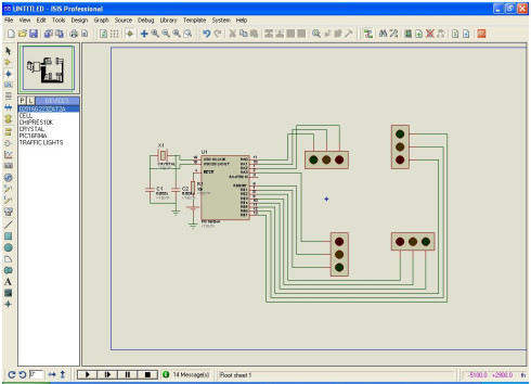
1) In this project we are going to operate (control) a four way traffic light signal using PIC16F84A microcontroller. First thing we have to do is , simply connect four set of Red-Green-Yellow LEDs to respective pins of PIC16F84A microcontroller as shown in circuit diagram(you can also use separate LEDs just connect all common terminals (negative) to ground with 330Ω resistor in series with each LED).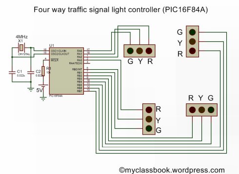
2) 5V supply to the pin number 14.
3) Ground pin number 5.
4) Connect two 22uF capacitors in parallel with two terminals of crystal oscillator.
5) Make all the remaining connection as shown in figure.
Click below link to download .C and .HEX files for this project
Source : Four way traffic light signal using PIC16F84A microcontroller:
- What is the main function of this project?
To operate a four way traffic light signal using a PIC16F84A microcontroller. - How many LEDs are required for the setup?
Four sets of Red-Green-Yellow LEDs are needed. - Which microcontroller is used in this project?
The PIC16F84A microcontroller is used. - What frequency does the crystal oscillator operate at?
The crystal oscillator operates at 4MHz. - How should the capacitors be connected?
Connect two 22uF capacitors in parallel with the two terminals of the crystal oscillator. - What voltage supply is required for pin 14?
A 5V supply is required for pin number 14. - Where should the ground connection be made?
The ground connection should be made to pin number 5. - Can separate LEDs be used instead of RGB sets?
Yes, you can use separate LEDs by connecting all common terminals to ground with a 330Ω resistor in series.